CNC machining · Aluminum alloy 5052
5052 Aluminum CNC Machining for Enclosures, Panels and Equipment Housings
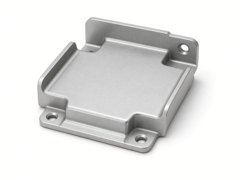
We machine 5052 parts to customer drawings for equipment manufacturers and enclosure buyers who value corrosion resistance, formability and lower weight than steel. We assess the part’s structure, material temper, wall thickness, holes and slots, and surface requirements before recommending a machining route.
From covers and mounting plates to brackets and machined panels, we plan for repeatability across prototypes and small-to-medium production runs.
3-, 4- & 5-axis
CNC milling options
ISO 9001
Certified quality system
±0.01 mm
Listed milling and turning equipment tolerance; part-specific capability is confirmed at quotation
±0.02 mm
Listed automatic-lathe equipment tolerance; part-specific capability is confirmed at quotation
Material fit
Where 5052 fits—and where it may not
5052 is non-heat-treatable; its strength depends on temper and work hardening. It cannot reach the strength levels of 6061-T6 or 7075-T6. We do not assume it suits every high-strength part: if a structural bracket or other load-bearing application appears better suited to another alloy, we raise that during drawing review.
5052 may fit when you need
- • Corrosion resistance in humid, marine or chemically exposed environments
- • Good weldability or formability, including parts that may be bent after machining
- • Lightweight covers and enclosures where stiffness comes from the design
- • A controlled surface appearance for anodizing or other finishes
How it differs in machining
Compared with 6061, 5052 can produce more gummy, stringy chips and build up on the cutting edge. We select tool geometry, cutting speeds and coolant strategy for the specific part rather than relying on one standard aluminum program.
| Alloy | Consider it when |
|---|---|
| 5052 | Corrosion resistance, formability or weldability is a priority and the design can provide the required stiffness. |
| 6061 | Higher strength, a heat-treated condition for structural loads or improved machinability for high-volume runs is needed. |
| 7075 | A higher strength-to-weight ratio is required and the environment and cost are appropriate. |
Drawing review
How we assess machining feasibility
Before quoting, we review how the part will be made and used. These details help us plan the setup, sequence, inspection and finish expectations.
01 · Material condition
Temper and stock form
We confirm temper, such as H32 or H34, and whether the stock is plate, sheet, bar or extrusion. Rolled or stretched stock can contain internal stress that releases during machining, particularly after substantial material removal or in thin sections.
02 · Geometry
Walls, pockets and unsupported features
Thin walls, deep pockets and long flanges are common sources of deflection. A 1.5 mm housing wall may meet a nominal drawing tolerance yet move under cutting or clamping forces. We assess wall height-to-thickness ratios and material removal on each side before setting the sequence.
03 · Features
Holes, slots and threads
Blind and deep holes need chip-evacuation planning. Tapped features in 5052 can gall if the tap and lubrication are not matched to the alloy. Where the design allows, we can recommend thread forms and minimum engagement lengths during review.
04 · Finish
Appearance and contact areas
For cosmetic, specified-finish or anodized parts, we review tool marks, edge quality and fixture contact points. Clamping marks and tool step-overs can remain visible after anodizing, so the process and expectations need to be clear.
Process control
Risks we plan for on 5052 parts
Thin sections and visible surfaces need deliberate machining and fixturing decisions. We discuss these risks during quotation rather than leaving them to final inspection.
Thin-wall distortion
Material removal can release stress and cause a thin section to bow. We may rough in stages, leave stock on critical surfaces, allow the part to rest before finishing, or use soft jaws and custom fixtures to spread clamping force.
Fixturing marks and cosmetic zones
Vise and clamp contact can mark soft aluminum. On visible surfaces, we consider soft jaws, protective inserts or clamping on non-cosmetic faces. If an area must remain mark-free, we note the datum and clamping approach on the quotation for confirmation.
Dimensional drift and repeat orders
Thermal growth during longer runs and tool wear can affect dimensions. For repeat orders, we set in-process checks at defined intervals and record measurements to identify drift before final inspection.
Burrs and edge condition
5052 can produce persistent burrs. We define the requested edge break, chamfer or hand-finish for specific edges in the quotation.
Manufacturing options
Machining routes for 5052 components
Our equipment base lets us select a process around the part instead of forcing every design onto the same machine.
| Process | Equipment | Typical 5052 parts |
|---|---|---|
| CNC milling | 3-axis machining centers (25 units), 4-axis (1), 5-axis (8) | Housings, mounting plates, covers and multi-sided brackets |
| CNC turning | CNC lathes (43 units), gang-type lathes (7) | Round housings, bushings, spacers and shafts |
| Turn-mill machining | CNC turn-mill machines (15 units) | Parts combining turned diameters with milled flats or holes |
| Swiss-type machining | 5-axis, 6-axis and other Swiss-type lathes (10 units) | Small, slender components and precision pins |
| Auxiliary operations | Conventional milling machines and small surface grinders | General milling and surface finishing |
Listed equipment tolerances are ±0.01 mm for milling and turning and ±0.02 mm for automatic lathes. Achievable tolerance on an individual 5052 part depends on its geometry, size and feature layout; we confirm it during quotation.
Inspection and quality
Verification planned from the drawing
We plan inspection around the drawing and job requirements, rather than adding it only at the end. Our quality system is certified to ISO 9001.
Available inspection resources include a coordinate measuring machine for 3D dimensional and geometric checks, five 2D optical measuring systems for profiles and hole positions, a concentricity measuring instrument, a surface roughness tester and a Rockwell hardness tester for material verification. Routine checks can also use height gauges, micrometers, calipers, pin gauges and thread gauges.
Inspection can be defined per job
- 01First-article reports where requested
- 02Periodic in-process checks to monitor dimensions and drift
- 03Material certification coordination with the material supplier when required
- 04Surface, thread and geometric checks based on drawing requirements
Prepare a quotation
What to send for a 5052 quote
With these details, we can assess feasibility, recommend a machining route and return pricing and lead time with the assumptions stated. If a drawing needs clarification, we ask specific questions rather than guess.
- 01PDF or STEP drawings with dimensions, tolerances and surface requirements
- 02Material specification, including temper such as H32 or H34 and stock form if known
- 03First-order quantity and expected annual or repeat volumes
- 04Finish and post-processing requirements, including anodizing, deburring and cosmetic zones
- 05Application environment: humidity, salt exposure, chemical contact and temperature range
- 06Inspection, traceability and documentation requirements
Common questions
Planning a 5052 part
Can 5052 hold tight tolerances in a thin-wall enclosure?
It depends on wall height and thickness, material condition, stock stress, clamping and the amount of material removed. We assess those details from the drawing and confirm achievable tolerances for the specific part rather than assume a general machine tolerance applies.
What should I specify for cosmetic or anodized surfaces?
Identify visible faces, required finish and any surfaces that must remain free of fixture marks. Tool marks, edge condition and clamping contact can affect appearance after anodizing, so clear cosmetic zones help us plan the setup and quotation.
Should I choose 5052 or 6061?
5052 is often considered for corrosion resistance, formability and weldability. 6061 may be a better fit when higher strength, a heat-treated structural condition or machinability for high-volume runs is important. The application and design determine the right choice; we can flag concerns during drawing review.
Request a machining quote
Send us your 5052 drawings and application details
Share the drawing, material temper and stock form if known, plus the application environment and required finish. We’ll review feasibility, discuss risks such as thin-wall distortion and cosmetic clamping marks, and provide a quotation based on the part and order quantity.
For prototype or small-batch work, include your target timeline so we can plan machine time. If the application may call for a different alloy, we’ll raise that before cutting material.
Include with your inquiry
- • Drawing files and critical tolerances
- • Material condition, including temper and stock form
- • Quantity, surface requirements and inspection needs
- • Application environment and target delivery timing