CNC Machining Quality
Quality Control Process for CNC Machined Parts
Most quality disputes on machined parts do not start on the shop floor. They start earlier, when a drawing revision is missed, a tolerance is read differently by two people, or an inspection requirement is never written into the purchase order.
Our quality control process is built around closing those gaps before cutting begins, then checking parts against the drawing at the points where deviations are most likely to appear. Where a step depends on what you request at quotation stage, we say so.
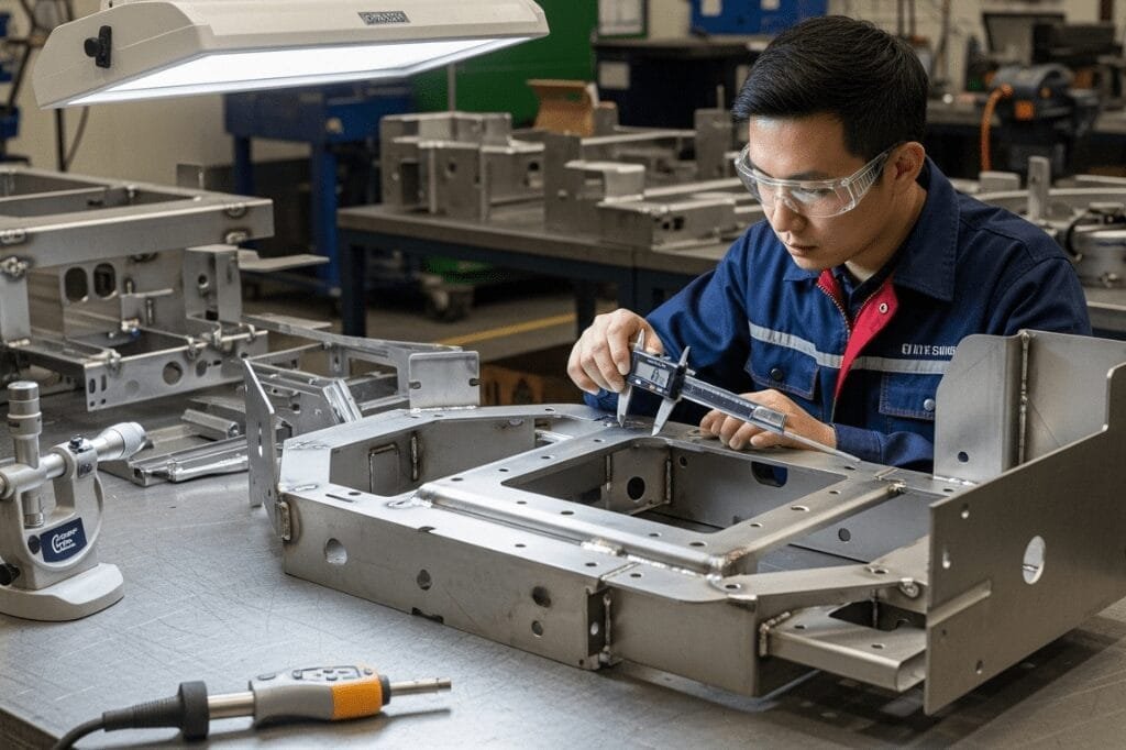
Our Process at a Glance
This page describes the steps we follow on customer projects, from the first drawing review to the final release of parts. The stages below follow the same order as our production workflow. Open each stage to see what we check and what we need from you.
Drawing and Specification Review
Before we quote, our engineering team reads the drawing and checks the features that will control cost and quality. We look for conflicts before they reach the shop floor.
We ask for the drawing revision level in writing and record it against the quotation. This single step prevents parts from being machined to a superseded drawing.
What we check
- Critical dimensions and geometric tolerances
- Thread specifications and surface finish callouts
- Notes that change how the part is made
Conflicts we look for
- Tolerances that cannot be held with the intended setup
- Datum schemes that do not match the functional requirement
- Finish requirements needing a secondary operation not shown on the drawing
If the drawing carries a revision that differs from the file you sent earlier, we confirm which one governs the order. Questions raised at this stage are returned to you as a written list. We do not start a production order on an assumption we have not confirmed.
Material and Drawing Confirmation
Before programming, we confirm the material specification, condition, and supplier documentation that applies to the order. Where material certification is required, we confirm the certificate type at quotation stage so it is requested from the material source in time.
We check the material grade and form against the drawing and record heat or lot information when the order requires traceability.
Filed together with the production order
- The released drawing and its revision level
- Any approved deviations
- Material records and traceability data where required
Operators and inspectors work from this controlled set, not from printed copies that may be out of date.
Machining Process Planning
Once the drawing and material are confirmed, we set the process plan. The machine and process for each feature are chosen against the tolerance and geometry on the drawing, not only against machine availability.
Process selection
CNC milling on 3-, 4-, or 5-axis machining centers, CNC turning, turn-mill machining, Swiss-type machining for slender or small-diameter parts, and screw machining for threaded fasteners.
Inspection points
For each critical feature we define when it is measured during the run, which gauge or instrument is used, and the acceptance limits.
Fixtures ready early
Features that cannot be checked without special fixtures are noted in the plan, so the fixture is ready before the first article is cut.
Datum preservation
For parts combining turning and milling, we sequence operations so datum references are preserved between setups. Datum loss is one of the most common reasons parts pass one inspection and fail another.
Process Stages in Detail
Open a stage to read how we handle production checks, measurement, and final release.
Operators measure parts at the intervals set in the process plan. Typical checks include diameter and length on turned features, hole position and depth on milled parts, thread gauging, and visual checks for burrs, scratches, or tool marks that the drawing requires to be absent.
When a measurement approaches a limit, the operator stops the run and notifies the supervisor. The cause is identified before production continues, whether it is tool wear, thermal drift, fixture movement, or an incorrectly entered program offset. We record the correction and check the first parts produced after it.
For longer runs, we verify that the process remains stable over time rather than checking only the first part. This matters most on batches where gradual drift can produce many out-of-tolerance parts before anyone notices.
Critical dimensions are measured with equipment matched to the tolerance. Features with tight geometric tolerances, such as position, runout, concentricity, or profile, are measured on the CMM or the concentricity instrument where possible, because hand gauging cannot confirm these reliably.
Simpler features may be checked with calipers, micrometers, or gauges during production, with the CMM used for periodic verification. If your drawing requires a measurement method not listed on this page, tell us during the RFQ stage. We will confirm whether we can meet it or whether it needs to be subcontracted.
Final inspection is performed on finished parts against the controlled drawing. The inspector checks the full set of dimensions and features called out on the drawing, not only those that were problematic during the run. Parts are separated by lot or order, and nonconforming parts are segregated and marked before any sorting decision is made.
Depending on order requirements, documentation may include a dimensional inspection report, material certificates, a first article inspection report, or a certificate of conformance. We confirm the format and content at quotation stage so the report matches what your supplier qualification or receiving process expects. If documentation is requested but not specified in the RFQ, we will ask before quoting rather than assume a format.
Inspection Equipment
Our inspection resources are matched to the tolerances we machine. The table below lists the equipment we use and what each is typically used for.
| Inspection Equipment | Quantity | Typical Use |
|---|---|---|
| Coordinate Measuring Machine (CMM) | 1 | 3D dimensional and geometric inspection |
| Optical measuring systems (2D vision) | 5 | Profile, hole position, and dimensional measurement |
| Height measuring instruments | 2 | Height and dimensional measurement |
| Concentricity measuring instrument | 1 | Concentricity measurement |
| Surface roughness tester | 1 | Surface roughness measurement |
| Rockwell hardness tester | 1 | Material hardness testing |
| Coating thickness gauge | 1 | Coating thickness measurement |
| Micrometers | 10 | Precision dimensional measurement |
| Thread ring and plug gauges | M1.0 to M16 sets | External and internal thread inspection |
| Pin gauges | 1.0 to 16.0 mm sets | Hole diameter and fit inspection |
Problems This Process Is Designed to Prevent
Most of the disputes we see trace back to a small set of causes. Each one has a specific control in our process.
Drawing revision errors
Parts made to a superseded drawing are a cost to everyone. We confirm the revision at order entry and again before the first part is released.
Unclear quality responsibility
When it is not written down who measures, who approves the first article, and who decides on nonconforming parts, disputes follow. We define these roles in the process plan and confirm them with you when the order is placed.
Machining deviations between batches
Tool wear, setup changes, and program edits can shift dimensions. Our in-process checks and first-article verification are intended to catch these shifts before a full batch is affected.
Final acceptance disputes
Many disputes come from different measurement methods or unclear acceptance limits. Agreeing on the measurement method, the instrument, and the inspection plan before production removes most of the ambiguity.
Which Projects This Process Suits
This process is most useful where dimensional accuracy, traceability, or documented inspection matters to your next step. That includes prototype parts used for design validation, production runs where repeat orders must match the first approved sample, and components for medical, aerospace, industrial equipment, robotics, and electronics applications.
It also suits procurement teams evaluating a supplier's inspection capability before qualification. The equipment list, certification scope, and sample inspection reports can be requested as part of that evaluation.
Certifications
Our quality management systems are certified to ISO 9001, ISO 13485, AS9100D, ISO 14001, and IATF 16949. Certification applies to defined scopes of activity, so please confirm the scope relevant to your part and industry in your RFQ.
Scope questions for your supplier file are welcome at any time.
What to Include in Your RFQ
Quality requirements are easiest to meet when they are stated before quotation. Including the items below lets us quote accurately and avoids follow-up delays.
- Drawing files in the released revision, with the revision level clearly stated
- Material specification and any required certification type
- Critical dimensions and features you consider functional or safety-related
- Required inspection documents, such as a first article inspection report, dimensional report, or certificate of conformance
- Customer-specific quality requirements, supplier quality manual, or sampling plan
- Expected annual volume and order frequency, so the inspection plan can be scaled appropriately
If you have a specific inspection plan or control plan, send it with the RFQ. We will review it against our process and tell you where we can meet it as written and where we would propose a change.
Send Us Your Drawings and Quality Requirements
If you are comparing suppliers for CNC machined parts, send us your drawings and quality specification. We will review the tolerances, confirm the process plan, identify any inspection requirements that need clarification, and return a quotation that states the documentation included.
Send your drawing files and quality requirements to info@yjcncmachining.com, or contact our team at Yabian Community, Shajing Street, Baoan District, Shenzhen, China to discuss a project.