CNC machining for demanding applications
PTFE CNC Machining for Seals, Bushings & Insulating Parts
PTFE is soft, slippery, and straightforward to cut—but its flexibility, creep, and thermal expansion can make finished dimensions difficult to control. We machine PTFE components to customer drawings and review the part’s operating conditions, mating fit, and critical tolerances before choosing a process.
A bore measured on the machine may change as the part relaxes or reaches assembly temperature. A thin seal can distort under clamping pressure, and a room-temperature bushing fit may change as the housing heats up. We account for these behaviors during our drawing and quotation review.
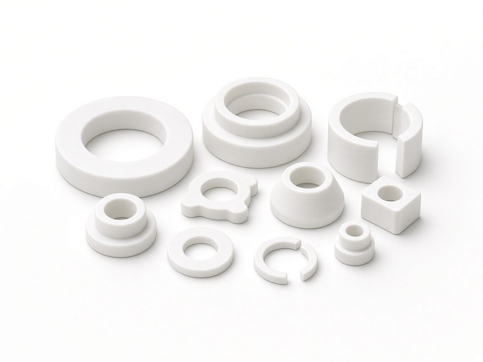
Machined around the application
We assess working temperature, media, load, sealing structure, and tolerance requirements before recommending a machining plan.
43
CNC lathes listed for turning
±0.01 mm
Listed precision on several machine types under suitable conditions
ISO 9001 · ISO 13485 · AS9100D · ISO 14001 · IATF 16949
Quality management system certifications; applicable scope confirmed on request
Material behavior
Why PTFE needs a different machining plan
We consider what the material does during cutting, inspection, assembly, and service—not just what the drawing says at room temperature.
Flexibility and spring-back
PTFE has a low modulus and low hardness compared with metals and many engineering plastics. Clamping pressure can deflect the workpiece, especially on thin walls and long sections. A bore may close while clamped and change after release, so we plan workholding to limit distortion.
Heat and surface finish
PTFE conducts heat poorly, concentrating cutting heat near the tool. Dull tools can rub, smear the surface, and affect finish. We use sharp tooling, controlled feeds, and air or minimal coolant to keep cuts clean, avoiding flood coolant when fluid or residue could affect later use.
Creep under sustained load
PTFE can slowly deform under load, even at moderate temperatures. A flange or seat may lose preload over time. We ask about operating load, clamping force, and preload early because these conditions can influence geometry, grade selection, and tolerance recommendations.
Thermal expansion and fit
PTFE’s linear expansion coefficient is roughly ten times that of steel. A 50 mm bore can change enough across a moderate temperature range to affect clearance, interference, or sealing pressure. We review assembly and operating temperatures alongside the mating materials and fit.
Material selection
PTFE grades and the trade-offs we review
We do not choose a grade on machinability alone. Fillers can improve stiffness, creep resistance, or wear behavior, but they also change other material properties. If the drawing does not specify a grade, we can review the application and suggest options for your engineering team to confirm.
Unfilled PTFE
Offers strong chemical resistance and electrical insulation among common grades, but has the highest creep and lowest wear resistance under load.
Glass-filled PTFE
Improves stiffness and reduces creep; often used for seal rings and valve seats. Its abrasiveness calls for attention to tooling and edge condition.
Carbon- or graphite-filled PTFE
Can improve wear behavior and thermal conductivity, and is often considered for bearings and sliding surfaces.
Bronze-filled PTFE
Can increase load capacity and thermal conductivity, but changes electrical properties and is not suitable when an insulating component is required.
No PTFE grade should be assumed suitable for every chemical medium or load condition. We need the service details to review material fit, and final material suitability remains the responsibility of the customer’s engineering team.
Process selection
We match the equipment to the geometry and order volume
We use a broad CNC equipment base to suit different PTFE part geometries instead of routing every job through the same machine. The precision figures below are listed machine capabilities under suitable conditions—not a guarantee for every finished PTFE feature.
| Process | Equipment | Quantity | Listed precision | Typical PTFE parts |
|---|---|---|---|---|
| CNC Turning | CNC Lathes | 43 | ±0.01 mm | Bushings, sleeves, seal rings, spacers |
| CNC Turning | Gang-Type CNC Lathes | 7 | ±0.01 mm | Small shafts, short bushings |
| Automatic Turning | Automatic Lathes | 30 | ±0.02 mm | Small pins, insulating inserts |
| Turn-Mill Machining | CNC Turn-Mill Machines | 15 | ±0.01 mm | Parts with turned and milled features |
| CNC Milling | 3-Axis CNC Machining Centers | 25 | ±0.01 mm | Plates, insulating spacers, brackets |
| CNC Milling | 4-Axis CNC Machining Center | 1 | ±0.01 mm | Multi-sided insulating parts |
| Swiss-Type Machining | 5-Axis, 6-Axis, and Other Swiss-Type Lathes | 10 | ±0.01 mm | Slender bushings and small-diameter parts |
Turning and turn-mill
We typically consider turning for rings, bushings, sleeves, and seal faces. Turn-mill work can finish parts with both turned and milled features in one setup.
Milling
Milling can suit plates, spacers, brackets, and parts with slots, flats, or cross holes. Very thin walls and deep, narrow slots may need a design review.
Swiss-type and automatic lathes
A Swiss-type guide bushing supports slender stock close to the cut, helping reduce deflection. Automatic lathes can suit higher-volume runs of small parts when repeatability is a priority.
Finished-part tolerances depend on geometry, wall thickness, grade, and workholding. We may recommend a tolerance band that accounts for thermal expansion and creep rather than the tightest number the machine can reach. Prototype and low-volume work may favor quick setups; higher-volume small parts may justify automatic lathes and fixed tooling.
Application review
Fit, sealing, and insulation depend on service conditions
Seals
Sealing depends on controlled contact pressure and surface finish. Because creep can reduce contact force over time, we review the sealing geometry and specified face roughness against the expected service conditions.
Bushings
We review housing material, operating temperature range, mating shaft finish, and the required bore-to-shaft clearance. PTFE expands more than metal housings, so room-temperature dimensions may need to account for operating fit.
Insulating components
Dielectric properties vary with grade, filler, and moisture. Unfilled PTFE is commonly used for electrical insulation, but filled grades may not be suitable. We do not assume a grade is insulating unless the drawing or material specification confirms it.
Chemical service
PTFE resists many aggressive media, but it is not suitable for every chemical environment. Some molten alkali metals, certain fluorinated compounds at high temperature, and other specific conditions can cause damage. Resistance depends on concentration, temperature, pressure, and exposure time. We need those details for review; final material suitability remains with your engineering team.
How we verify PTFE dimensions
PTFE can change after machining as the part relaxes or equilibrates to room temperature. We plan inspection around stabilization and record measurement conditions when the drawing requires it.
- 01Geometric checks: coordinate measuring machine for three-dimensional and geometric inspection.
- 02Profile and position: optical measuring systems for profiles and hole position; concentricity instrument for turned bushings.
- 03Surface and routine dimensions: roughness tester for sealing and sliding surfaces, alongside calipers, micrometers, height gauges, and pin gauges.
- 04Fit and records: gauge pins or sample mating parts when fit matters; inspection records can be provided to match drawing requirements. Thread gauges cover external and internal threads from M1.0 to M16.
Our quality management system is certified to ISO 9001, ISO 13485, AS9100D, ISO 14001, and IATF 16949. We can confirm applicable certification scope on request; scope does not extend to every product or process we run.
RFQ checklist
What to send with your PTFE machining request
Complete inputs help us evaluate material behavior, workholding, tolerance, and process options before quoting. If some details are not yet available, send what you have; we can identify which missing information could change the recommendation.
Share your part detailsPart definition
- Engineering drawing in PDF or STEP format
- Critical dimensions and tolerances marked
- Mating part drawing or fit requirement for seals and bushings
- Required surface roughness on sealing or sliding faces
Material and service
- Material grade, including filler type and percentage if known
- Operating temperature range and thermal cycling
- Contact medium or fluid, concentration, and pressure
- Expected load, clamping force, or preload
Inspection and production
- Inspection requirements, such as first-article reports or dimensional records
- Expected annual volume and order frequency
- Any additional assembly or operating fit requirements
- Known restrictions on coolant, residue, or handling
Design for manufacture
Early review can flag difficult PTFE features
Very thin walls, deep narrow slots, and internal features with tight clearance to adjacent parts can be challenging in PTFE regardless of machine choice. If we see a risk, we’ll raise it during review and discuss options such as increased wall thickness, a split design, or a stiffer filled grade where the application allows.
We review the part as a complete assembly requirement: temperature, medium, load, sealing structure, and tolerance all inform the machining approach. Our process and tolerance comments are recommendations for your engineering team to evaluate against the design intent.
Request a quotation
Let’s review your PTFE component
Send us the part drawing, material grade, service medium, and critical dimensions. We’ll review the application and return process recommendations, tolerance comments, and a quotation. If your design is still in development, we can also review manufacturability before release.
Helpful details to include
Drawing in PDF or STEP format · PTFE grade · operating temperature · medium and pressure · load or clamping force · key fit dimensions
Our facility is located at Yabian Community, Shajing Street, Baoan District, Shenzhen, China. Contact YJCNC by email at info@yjcncmachining.com to arrange a technical discussion.
Send your inquiry
Use the contact form to share your drawing and application requirements.
Common questions