CNC machining guide
3-Axis vs 5-Axis CNC Machining: Which Process Fits Your Part?
Choosing an axis count is not simply a choice between basic and advanced machinery. We compare geometry, tool access, setups, tolerances, programming, and total cost so you can identify the process that makes sense for your part.
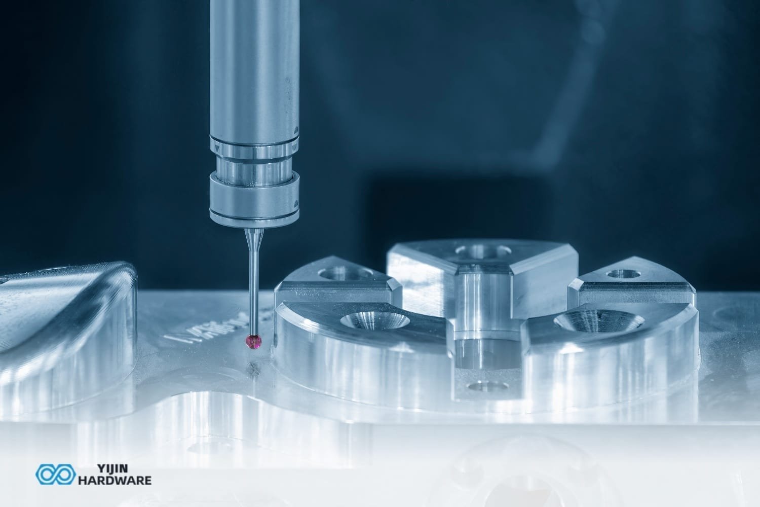
Quick Answer: Which Process Should You Choose?
Choose 3-axis machining for prismatic parts with features that are easy to reach from the top or a small number of sides. Choose 5-axis when complex contours, undercuts, compound-angle features, or tight relationships between multiple faces make access and setup count important. For a part that needs to rotate around one primary axis, 4-axis may provide a practical middle ground. The best choice comes from the part’s geometry and inspection requirements—not the axis count alone.
Start with 3-axis
Flat faces, straight walls, and top-accessible pockets dominate the design.
Consider 5-axis
Angled access, undercuts, sculpted surfaces, or multi-face tolerances drive the process.
Check the middle ground
A single rotary axis may be enough for cylindrical or repeat multi-face features. Further process detail lives under aerospace multi-axis needs.
For a quick first pass, use the decision checklist below, then review the drawing’s datums, tolerances, and critical surfaces with your manufacturing partner.
Shop context
How we decide 3-axis vs 5-axis from the drawing
- Count setups and datum handoffs: compound faces that must stay true to one another often justify 5-axis even if a 3-axis rate looks cheaper.
- Undercuts, deep angled holes, and five-side access in one clamp are the usual 5-axis triggers; prismatic plates and simple pockets stay on 3-axis.
- Send the model with GD&T datums marked—we propose axis count and fixture approach with the quote, not after scrap shows up.
What Axis Count Means in CNC Machining
The axis count describes the directions in which the cutting tool or workpiece can move under machine control. The three linear axes are X, Y, and Z: movement side to side, front to back, and up and down. Rotary axes are commonly named A, B, and C, referring to rotation around the X, Y, and Z axes. A machine’s available motion influences the tool’s approach angle, the features it can reach, and how often the part must be repositioned. For terminology, see Five-axis machining.
How 3-Axis Motion Works
On a 3-axis milling machine, the cutter moves along X, Y, and Z while the part is held in a fixed orientation during a cutting operation. This is well suited to milling faces, slots, and pockets that the tool can reach from that direction. To machine another side, an operator or automated process must reorient and secure the workpiece again.
Setup detail
Every repositioning requires a repeatable locating method. A fixture and datum plan help control alignment, but each additional clamping step still adds time and another opportunity for variation.
How 5-Axis Motion Works
A 5-axis machine combines the three linear axes with two rotary axes. Depending on the machine configuration, the rotary motion may come from the table, the tool head, or a combination. This lets the cutter approach a part from many directions without removing it from the machine, improving access to angled surfaces and some undercut geometries.
There are two common ways to use that motion. With indexed 5-axis, often called 3+2, the rotary axes position the workpiece or tool at an angle, then the machine cuts using the three linear axes. For example, a block with holes on several angled faces can be indexed to each face and machined in one clamping. With simultaneous 5-axis, the rotary axes move during cutting along with the linear axes; this can follow a changing surface such as an impeller blade or a sculpted mold form.
Where 4-Axis Fits
A 4-axis mill adds one rotary axis to the three linear axes. It can rotate a part to access multiple sides or machine features distributed around a cylinder, such as holes or slots around a shaft. If the part needs controlled rotation around one axis but does not require the additional orientation freedom of 5-axis, 4-axis can be a cost-effective middle ground. The geometry and feature locations determine whether that single rotary axis is sufficient.
3-Axis CNC Machining: Strengths, Limits, and Typical Uses
3-axis CNC milling is a common choice for straightforward components made on vertical or horizontal machining centers. A stable workholding setup and a clear datum structure make it an efficient way to produce many prismatic designs, from mounting plates to housings. Our CNC milling capability includes 3-axis machining centers used for components such as brackets, housings, and mounting plates.
Parts Best Suited to 3-Axis
Consider 3-axis for brackets, plates, enclosures, fixtures, and housings when the important features are accessible from the top or a small number of sides. It is often a good fit when the design has flat faces, straight walls, and pockets that can be reached with standard tool orientations. More examples of reachable prismatic work are covered in what a 3-axis machine can make.
A useful geometry screen
- Most critical features are visible from one direction.
- Pocket walls are straight and the cutter can reach the floor.
- Any side features can be handled with a simple, repeatable re-fixture.
Typical examples
A flat mounting bracket with drilled and tapped holes, or a housing with open-top pockets and a machined perimeter, may be economical on 3-axis when the datum scheme and side access are manageable.
Advantages of 3-Axis Machining
3-axis machines generally have lower hourly rates than 5-axis equipment, and their programming and setup planning are often more direct for simple geometry. That can support faster quoting and shorter lead times when a part needs only a few operations. The broad availability of machines and experienced operators can also make this process practical for prototypes, repeat orders, and production parts with accessible features. For terminology, see Numerical control.
Limitations of 3-Axis Machining
The main limitation is access. A component with features on several sides may need multiple setups, each requiring reorientation and location. Deep cavities, undercuts, and compound-angle surfaces can be difficult or impossible to reach with a straight tool approach. Long tools used to reach deep features may also deflect more, making dimensional control and surface finish harder to manage.
A 3-axis approach can still make a complex part through custom fixtures, carefully planned operations, and inspection between setups. The question is whether those extra operations make sense compared with an indexed or simultaneous multi-axis route.
5-Axis CNC Machining: Capabilities and Trade-Offs
5-axis machining changes the available tool orientation, which can reduce the number of times a part must be removed and re-clamped. It is particularly useful when a component has complex contours, angled faces, or features spread around multiple sides. The process does not eliminate the need for sound workholding or inspection, but it can make difficult geometry more accessible within a single clamping.
Parts Best Suited to 5-Axis
Impellers, turbine blades, medical implants, aerospace structural components, and mold cores can contain sculpted surfaces or features that change angle across the part. 5-axis machining can also suit components with undercuts, multi-angle holes, or several faces whose relationships must be controlled without repeated manual repositioning.
Indexed vs. Simultaneous 5-Axis
Indexed: orient, then cut
The machine positions the rotary axes at a selected angle and then performs a 3-axis cut. This approach is often easier to program and verify, and can work well for a prismatic part with angled faces or holes.
Simultaneous: move through the cut
The rotary axes keep moving while the tool follows a contour. This supports continuous machining of organic surfaces, but requires more demanding toolpath planning, post-processing, and collision verification.
Advantages of 5-Axis Machining
- Fewer setups: machining multiple faces in one clamping can reduce the setup-to-setup alignment variation that affects cross-face relationships.
- Improved access: the tool can approach angled faces more directly, which may avoid long-reach tooling on some features.
- Better control of surface contact: an appropriate tool orientation can support a more consistent finish and tool engagement on complex contours.
- Complex geometry in one clamping: a suitable machine and program can reach features that would otherwise require multiple fixtures or operations.
Limitations of 5-Axis Machining
5-axis machine rates and programming costs are typically higher, and successful production depends on appropriate machine capability, skilled programming, and careful collision checking. Workholding can be more involved because the fixture must allow tool and machine motion while securely supporting the part. For simple, top-accessible parts, these added requirements may not deliver enough benefit to offset the extra cost and planning. Background on multi-axis access is also in what 5-axis CNC machining is used for.
Side-by-Side Comparison
Use this comparison as a starting point, not as a substitute for reviewing the model and drawing. A capable shop may achieve a good result with either approach when the part is designed and fixtured appropriately.
| Factor | 3-Axis | 5-Axis |
|---|---|---|
| Setup count | One setup for accessible features; more to reach additional faces. | Can machine multiple faces in one clamping when the setup allows. |
| Typical geometry | Prismatic shapes, plates, brackets, and open pockets. | Sculpted surfaces, angled features, and some undercuts. |
| Accuracy across faces | Depends on re-fixturing, datum transfer, and inspection. | Fewer re-clamps can help preserve positional relationships. |
| Surface finish | Strong for accessible surfaces with suitable tooling and parameters. | Tool orientation can help maintain effective contact on complex contours. |
| Tool access | Straight tool approach; deep or angled access may be limited. | More approach directions, subject to fixture and collision limits. |
| Programming effort | Usually simpler for straightforward geometry. | More involved, especially for simultaneous toolpaths. |
| Machine cost | Generally lower hourly rate. | Generally higher hourly rate and programming cost. |
| Best-fit volume | Often attractive for simple, low-volume parts and repeatable production. | Can suit complex parts at varied volumes when setup savings matter. |
Actual results depend on part design, material, tolerance scheme, workholding, machine condition, CAM capability, and the shop’s experience with the process.
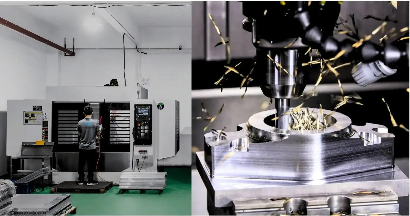
Key Decision Factors
When we review a part for manufacturability, we start with the questions below. The answers help identify whether extra rotary motion solves a real production problem or simply adds cost and complexity.
Part Geometry and Undercuts
Can every critical feature be reached from one direction, or with a straightforward reorientation? If not, look closely at undercuts, changing surface angles, and features hidden behind a wall. These are common reasons to consider 5-axis, although some designs can be changed to make the geometry easier to machine.
Tool Access and Reach
Will the cutter reach the feature without an excessively long tool or interference with nearby walls and workholding? Deep pockets and narrow cavities raise the tool length-to-diameter ratio, which can increase deflection and make vibration or poor finish more likely. A different approach angle may improve access, but collision risk must be checked against the tool, holder, spindle, fixture, and part.
Number of Faces and Setups
How many sides need machining, and how accurately must their features relate to one another? Each additional setup requires locating and securing the part again. That adds handling and programming time and can introduce setup-to-setup variation. A 5-axis machine may reduce re-clamping; it does not remove the need to define sound datums and verify the result. Fixture strategy matters as much as axis count—see jigs vs fixtures for CNC setups.
Tolerances and GD&T
Do position, profile, or orientation tolerances connect features on multiple faces? If so, reducing the number of setups can help maintain relationships between those features. Review the datum reference frame and inspection method alongside the axis strategy. Axis count by itself does not guarantee tolerance capability; machine condition, workholding, cutting strategy, and measurement all matter. For drawing callouts and stack-up habits, see how we approach tight tolerances.
Surface Finish and Tool Life
Are there visible or functional surfaces where cutter marks, tool engagement, or access affect performance? A suitable tool orientation on a 5-axis machine can improve contact on curved surfaces or allow a shorter tool on a particular feature. For straightforward faces, a 3-axis process may already deliver the required finish. Specify the finish requirement on the drawing where it is functionally important.
Production Volume and Lot Size
Is this a one-off prototype, a small batch, or a repeat order? Low-volume work often favors a simple route that can be programmed and set up quickly. Higher volumes can justify more elaborate fixtures, toolpaths, or automation when they reduce cycle time and improve repeatability. But a complex part may still benefit from 5-axis even in a small quantity if several 3-axis setups would be difficult or risky.
Total Cost: Machine Rate vs. Setup Time
Compare the full route, not just the hourly machine rate. Include programming, fixtures, setup, machining, deburring, inspection, and the risk of rework. The example below uses hypothetical cost units to show the arithmetic; it is not a YJCNC price, quote, or typical rate.
| Illustrative route for one complex part | 3-Axis route | 5-Axis route |
|---|---|---|
| Assumed machine cost unit | 1.0 unit per hour | 1.6 units per hour |
| Setup plus machining time | 6 hours total | 3 hours total |
| Illustrative machine cost | 6 cost units | 4.8 cost units |
In this simplified example, the higher-rate machine costs less because it removes enough setup and machining time. A real comparison needs the actual process plan, quantity, programming time, fixture costs, and inspection requirements for your part.
Industry Applications
Axis selection follows the part’s functional geometry and production requirements, not an industry label. These examples show how common priorities can influence the decision.
Aerospace
A structural bracket with accessible faces may be a 3-axis candidate, while an impeller or complex contoured component may need 5-axis access. For both, engineers should consider tolerance stack-up across faces, material utilization, traceability, and inspection requirements. We support aerospace supply-chain projects under our certified QMS (ISO 9001 (HIC241500), ISO 14001 (HIC241501), AS9100D/EN9100 (CN044900), ISO 13485 (04526MDQ00014R100), and IATF 16949 (0565487)), subject to the applicable scope and project requirements.
Medical Devices
Orthopedic implants and surgical instruments can combine curved surfaces, small features, and demanding finish requirements. A 5-axis process may help reach changing contours, while simpler instrument components may suit 3-axis or another process. Material selection, drawing requirements, surface finish, documentation, and inspection should be reviewed together. Our quality management systems cover ISO 9001, ISO 14001, AS9100D/EN9100, ISO 13485, and IATF 16949 (certificate numbers: ISO 9001 (HIC241500), ISO 14001 (HIC241501), AS9100D/EN9100 (CN044900), ISO 13485 (04526MDQ00014R100), and IATF 16949 (0565487)), subject to the applicable scope for medical and other regulated work.
Automotive and Tooling
Automotive prototypes, fixtures, and mold inserts may need a balance of lead time, dimensional repeatability, and surface access. A simple fixture plate can often be machined efficiently on 3-axis equipment; a contoured mold core or multi-face insert may benefit from 5-axis machining. For repeat work, evaluate the complete setup and inspection plan rather than assuming the first-part route is automatically the best production route.
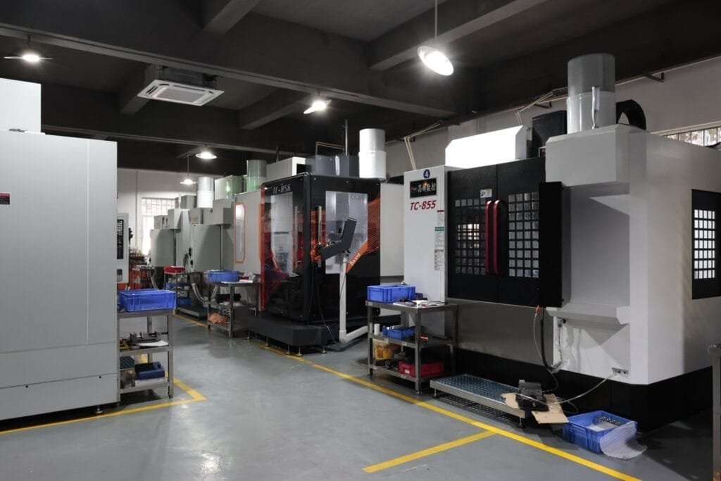
Programming and CAM Considerations
Choosing an axis strategy changes more than the machine assignment. It affects the CAM workflow, post-processing, setup definition, and verification required before a first part is cut.
3-Axis CAM Workflow
A 3-axis CAM plan typically starts by defining the work coordinate system, stock, fixture, and machining setups. The programmer selects toolpaths for facing, roughing, pocketing, drilling, and finishing, then checks tool reach and material remaining. Simulation helps review the cutting sequence and identify tool or fixture interference before the program is sent to the machine.
5-Axis Toolpaths and Collision Checking
A 5-axis program must also control how the tool is oriented. The programmer may define tool-axis direction, lead and tilt angles, rotary limits, and safe transitions between cuts. Because the tool, holder, head, table, fixture, and workpiece move in relation to one another, collision checking should consider the full machine setup—not only the cutter tip against the model.
Digital Twin and Simulation Tools
A virtual machine simulation can reveal potential collisions, motion-limit problems, or an unsafe toolpath before machining begins. That makes it a useful risk-reduction step, especially for complex simultaneous 5-axis work. Simulation supports—not replaces—experienced review, correct post-processing, machine setup verification, and first-article inspection.
3+2 Indexed vs Simultaneous 5-Axis: Which Route Fits?
Many drawings that “need 5-axis” are solved with indexed 3+2 (orient, then cut) rather than full simultaneous motion. Use the table below to shortlist a route before you compare machine-hour rates. Related capability notes live under CNC machining and CNC milling.
| Decision factor | 3-axis | 3+2 indexed | Simultaneous 5-axis |
|---|---|---|---|
| Typical geometry | Prismatic faces, top-access pockets, straight holes | Angled faces/holes; multi-side features that stay planar once indexed | Sculpted surfaces, continuous compound contours, undercuts that need tool tilt mid-cut |
| Setups / datums | Often multiple clamps; datum handoff risk across setups | One clamp, several fixed orientations; good for cross-face position | One clamp with continuous orientation; strongest for profile/contour continuity |
| Programming / prove-out | Simplest CAM and verification | Moderate; verify each index and clearance | Highest CAM/post/collision burden |
| Cost drivers | Fixture count and re-clamp time | Lower fixture count than multi-setup 3-axis; machine rate above plain 3-axis | Higher machine rate + programming; pay only when contour access truly needs it |
| Choose when… | Features reachable with one or two straightforward reorientations | Angled holes/faces dominate; little continuous sculpting | Tool must tilt while cutting to hold finish, access, or cycle time |
If your model only needs discrete angles, ask for a 3+2 quote before specifying simultaneous 5-axis. If continuous wall finish or organic surfaces drive the design, simultaneous is the honest starting point—and the drawing’s GD&T and inspection plan should reflect that.
Decision Framework: Which Process Is Right for Your Part?
Use the following rules of thumb to shortlist a process. If your part has features from more than one category, share the model and drawing so the manufacturing team can compare routes and explain the trade-offs.
Choose 3-Axis When
- Features are mostly accessible from the top or one or two sides.
- The required tolerances can be maintained with a small number of stable setups.
- The part is relatively simple, especially for a low-volume prototype or short run.
Choose 5-Axis When
- The part includes undercuts, sculpted surfaces, or compound-angle holes.
- Multi-face positional or profile relationships must be controlled with minimal setup stack-up.
- Tool reach, surface finish, or access angle is a major concern.
When 4-Axis Is the Better Middle Ground
Choose 4-axis when the component has cylindrical features or a series of features around one primary axis, but does not require the broader orientation flexibility of 5-axis. For example, a part that needs milling at several positions around a shaft may be suited to a rotary table. Confirm that the rotary travel, workholding, and tool access match the geometry.
Decision Checklist
Answer yes or no to each question. Each answer points toward a process to discuss—not a substitute for a drawing review.
-
1
Are all critical features reachable from one direction?
Yes: start with 3-axis. No: review 4-axis or 5-axis access.
-
2
Does the part have undercuts or changing surface angles?
Yes: consider 5-axis or a design change to improve access.
-
3
Are features distributed around a cylinder or one main rotary axis?
Yes: ask whether 4-axis can handle the feature pattern.
-
4
Must multiple faces hold tight positional relationships?
Yes: compare a one-clamping 5-axis route with multi-setup alternatives.
-
5
Would a long tool be needed to reach a deep, narrow feature?
Yes: review tool deflection, access angle, and a possible 5-axis approach.
-
6
Is the required surface finish on a complex contour?
Yes: assess simultaneous 5-axis tool orientation and finishing strategy.
-
7
Will the part be made repeatedly or in a larger lot?
Yes: compare the full production route, including fixtures, cycle time, and inspection.
-
8
Does the part need only one rotary axis to access its features?
Yes: include 4-axis in the quote comparison as a potential middle ground.
Frequently Asked Questions
Is 5-axis machining always more accurate than 3-axis?
No. Fewer setups can improve positional relationships across faces, but accuracy also depends on machine condition, calibration, workholding, programming, cutting strategy, and inspection. A well-planned 3-axis process may be the right choice for a part with accessible features.
Does 5-axis machining cost more per part?
Its hourly rate and programming costs are generally higher, but fewer setups can lower the total cost for a complex part. Ask for a comparison that includes programming, fixtures, machining, inspection, and quantity—not just the machine rate.
Can a 3-axis machine make complex parts?
Yes, sometimes. Additional setups, custom fixtures, and careful datum transfer can make complex components possible. Deep cavities, inaccessible undercuts, and compound-angle features may remain difficult or uneconomical, so compare the full process route before deciding.
Is 5-axis machining faster than 3-axis?
It depends on the cutting cycle, setup count, and programming time. A 5-axis route may be faster overall when it replaces several setups or enables a more direct cut. For a simple part, 3-axis may be quicker to program and manufacture.
What design changes reduce machining cost on either process?
Add tool-access radii where function permits, avoid deep narrow pockets, standardize hole sizes, and limit tight tolerances to features that are genuinely critical. Clear datums and sensible access can reduce setup complexity and make inspection more straightforward.
How do I get a quote for both options?
Send a 3D CAD file and drawing with material, tolerances, quantity, surface-finish requirements, and any inspection or documentation needs. If you have a preferred datum scheme or critical features, identify them. Ask the supplier to compare 3-axis, 4-axis, and 5-axis routes where practical so you can review both cost and risk.
Next Steps: Get a DFM Review for Your Part
The right process depends on whether your features are accessible, how many setups the part needs, how critical the relationships between faces are, and what the complete production route costs. A straightforward design may be best suited to 3-axis; a part with complex access or demanding multi-face requirements may justify 5-axis; and a single rotary axis may make 4-axis the practical choice.
We review customer drawings and specifications to help select an appropriate machining process and inspection approach. Our capabilities include CNC milling, multi-axis machining, turning, turn-mill, and Swiss-type machining for prototype and production requirements.
Request a DFM review and quoteTalk with our engineering team
Share your CAD file, drawing, material, quantity, and critical requirements. We can review whether 3-axis, 4-axis, or 5-axis machining is the best fit for your part.
We are certified to ISO 9001 (HIC241500), ISO 14001 (HIC241501), AS9100D/EN9100 (CN044900), ISO 13485 (04526MDQ00014R100), and IATF 16949 (0565487). Confirm which certificates apply to your drawing package and end-use before release.