Engineering Guide
Aerospace CNC Machining: Tolerances, Materials, and Quality Requirements
How tolerances, material choices, process planning, and documented quality control work together when a machined part has to perform in an aircraft or spacecraft, and what buyers should look for in a machining supplier.
Aerospace CNC Machining at a Glance
Precision machining sits behind many of the parts that keep aircraft and spacecraft safe: structural fittings, brackets, housings, engine-area components, and fluid-system parts. Each of these parts has to fit, carry load, and survive temperature and vibration exactly as the engineering design intended. A dimension that drifts by a few hundredths of a millimeter can turn into an assembly problem, a leak path, or a fatigue concern years later.
In this guide we walk through the decisions that matter most when you specify or buy aerospace machined parts: how to set tolerances that reflect function, how material selection shapes machining and inspection, which quality documents to expect, and how to judge whether a supplier can deliver consistently.
Tight tolerances are not a quality guarantee on their own. The best aerospace parts come from tolerances that match function, a material and process chosen for the job, and inspection evidence that anyone can trace back to the drawing.
Key considerations
Tolerances, material selection, process capability, and documented quality control. Treat these four as one connected plan rather than four separate purchasing questions.
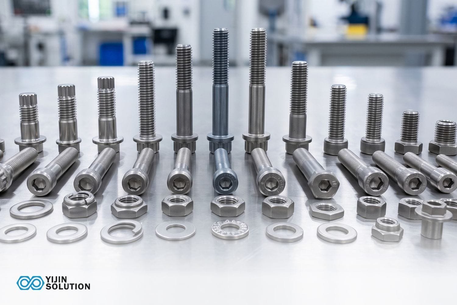
What Makes Aerospace CNC Machining Different?
A general CNC component is usually judged on whether it fits and functions in its immediate application. An aerospace part is judged on that too, but it also has to prove how it was made. Performance demands are higher, traceability reaches back to the material lot, and the documentation package often matters as much as the part itself.
Requirements also vary. The part function, the drawing, the customer, and the program each set their own limits, so two brackets that look identical on a shop floor can carry very different inspection and record obligations.
Typical aerospace and aerospace-adjacent applications we see in machining work include:
Structural fittings and brackets
Load-carrying parts where hole position, flatness of mounting faces, and material condition drive both fit and service life.
Housings and engine components
Parts exposed to heat, vibration, and tight interfaces with mating hardware, where bore positions and surface condition matter.
Fluid-system parts
Fittings and manifolds where internal passages, thread quality, and sealing faces must be controlled to keep fluids where they belong.
Turned and small precision parts
Shafts, bushings, pins, and connectors whose concentricity, diameter fit, and thread quality affect assembly and function.
Shop context
What aerospace drawings force us to confirm early
- Material callouts (aluminum, titanium, stainless, nickel alloys) and heat-treat/temper state drive both process plan and inspection depth.
- Tight positional and profile callouts need a datum scheme we can actually fixture—ambiguous datums show up as quote risk, not shop-floor heroics.
- We map AS9100D-scoped process controls and cert pack needs (material certs, FAIR/FAI expectations) against the drawing package before production release.
Aerospace CNC Machining Tolerances
A dimensional tolerance is the permitted variation from a nominal dimension. It is the band between the largest and smallest acceptable size of a feature. The tolerance you assign should follow the feature's job: a sliding fit, a clamped joint, a sealing surface, and a cosmetic face each need different control, and none of them should be dimensioned the same way by default.
Standard tolerances are the general limits that a shop can hold on common features without special attention. Tight or critical tolerances are limits set on features where fit, alignment, sealing, or load path depend on a narrow band. Critical tolerances cost more, so they should be reserved for features that truly need them.
Warning
Specifying every dimension at the tightest band is one of the most common and expensive drawing mistakes. It raises machining time, inspection effort, and scrap risk without adding functional value on most of the features it touches.
Tolerance decisions are shaped by how the part is used. Four questions help frame them:
Fit and assembly
Does the feature mate with another part, and does clearance or interference need to stay within a defined range?
Load path
Does the feature carry or transfer load, where misalignment could shift stress into an unintended location?
Temperature and environment
Will the part expand, contract, or see corrosive media in service, and does the drawing account for that behavior? For adjacent process context, see AS9100D.
Operating life
Does wear, vibration, or repeated assembly require a tighter control on a particular surface or hole?
Tolerance choices also ripple through the whole job. A tighter band can add machining passes, slower feeds, more tool changes, and additional in-process checks. It also increases the inspection time needed to prove conformance and raises the chance that a single out-of-band feature scraps an otherwise good part.
GD&T and Aerospace Engineering Drawings
Geometric dimensioning and tolerancing (GD&T) describes how features relate to each other, not just how big they are. Datums define the reference frame that the part is measured from. Position controls where a hole or feature sits relative to those datums. Flatness controls how close a surface is to a true plane. Profile controls the shape of a surface or edge within a defined zone.
A plus-or-minus dimension on two holes can be met while the holes still fail to line up with a mating part. GD&T closes that gap by tying the holes to a datum scheme that reflects how the assembly actually locates the part. That is why we review datum selection early when a drawing arrives.
Drawing discipline
Confirm the drawing revision, units, notes, acceptance criteria, and any referenced specifications before quoting or setting up a job. A mismatch between revisions is one of the fastest ways to lose a production lot.
Factors That Affect Achievable Tolerances
The tolerance a drawing asks for is a target. What a shop actually holds depends on the whole system. Our listed precision on milling and turning equipment is ±0.01 mm, but the tolerance achieved on a specific feature still depends on the factors below.
Machine capability
Thermal state, spindle condition, and axis accuracy determine what a given machine can repeat.
Tool condition
Worn or deflecting tools change size, finish, and roundness, especially on long reaches and hard materials.
Workholding
Clamping force and fixture location can distort thin or flexible parts before a cut is even made.
Material behavior
Residual stress, thermal conductivity, and springback vary by alloy and by the stock condition received.
Part geometry
Thin walls, deep pockets, and long slender sections are harder to hold steady than compact blocks.
Operator and process control
Documented setups, offsets, and in-process checks keep results repeatable from one shift to the next.
Several conditions are especially hard to control. Thin walls deflect under cutting force and spring back after the clamp is released. Long parts can sag or chatter. Heat builds in the cut and in the part, so a dimension measured warm may read differently once the part cools. Vibration leaves marks and size variation, and distortion can appear after machining as internal stress relaxes, which is why we plan stress relief and roughing-to-finishing sequences for sensitive parts.
Setup strategy and in-process measurement are the main levers. Fewer setups reduce the number of times a datum must be re-established. Probing and in-process checks catch drift before a whole batch is affected. Together they narrow the spread that a final inspection would otherwise have to catch.
Materials Used in Aerospace CNC Machining
The common aerospace material families are aluminum alloys, titanium alloys, nickel alloys, and stainless steels. Selection depends on the design requirements of the part and on the approved material specification named in the drawing or program. Machinists do not choose the alloy on their own; the design does, and our role is to machine it reliably.
The table below summarizes how these families compare in general terms. Real decisions should always reference the specification and the actual part conditions.
| Material family | Machinability | Strength-to-weight | Corrosion and heat resistance | Relative cost |
|---|---|---|---|---|
| Aluminum alloys | Generally high; fast cutting | Good for lightweight structures | Moderate; surface protection often specified | Lower |
| Titanium alloys | Demanding; heat and tool wear | Very good | Good corrosion resistance and heat capability | Higher |
| Nickel alloys | Difficult; slow cycle times | Strong at elevated temperature | Excellent heat and corrosion resistance | Higher |
| Stainless steels | Moderate; work hardens | Good strength, heavier than aluminum or titanium | Good corrosion resistance | Moderate |
Aluminum Alloys
Aluminum is the workhorse for lightweight structural brackets and housings. It machines quickly, chips cleanly, and offers a favorable strength-to-weight ratio for many structural applications. For parts with large material removal, its machinability often shortens cycle time significantly compared with harder alloys.
Alloy choice still matters. Machinability and response to heat treatment differ between alloy designations, and the specified temper affects how much the part moves after roughing. Surface protection, such as the anodizing or coating the drawing calls out, should be planned into the dimensions from the start, because treatments add material thickness or change how a feature gauges.
Titanium Alloys
Titanium offers an excellent strength-to-weight ratio and performs well in demanding environments where corrosion and elevated temperature matter. Those same properties make it harder to cut. It conducts heat poorly, so the heat concentrates at the cutting edge and accelerates tool wear.
Practical titanium work depends on controlled cutting parameters, sharp and well-maintained tooling, rigid workholding, and enough coolant to manage heat at the cut. Tool wear is tracked deliberately, because a dulling tool changes size and surface condition gradually. Rigid setups and careful toolpath planning reduce chatter that would otherwise show up as dimensional and finish problems.
Nickel Alloys and Stainless Steels
Nickel alloys are chosen where heat, corrosion, and high-temperature strength are demanding, such as engine-area hardware. Stainless steels are used where corrosion resistance and structural strength are needed in a more conventional package. Both families bring cutting characteristics that change process planning.
Nickel alloys typically require slower cutting speeds, robust tooling, and longer cycle times, which affects both cost and scheduling. Stainless steels can work-harden if the tool rubs instead of cutting, so feed and engagement have to be planned to keep the cut clean. In both cases, process planning should account for tool life, tool inventory, and the number of setups needed to hold the required geometry.
Material Certification and Traceability
Aerospace material control starts at receiving. Material specifications define the required chemistry, condition, and properties. Certificates of conformance or material test reports tie the stock to that specification. Heat numbers or lot numbers link each piece of stock back to its production source, so that a question about a part can be answered by tracing the record.
Substitution rule
A material substitution is never a shop-floor decision. It requires written authorization from the customer or program, and the substitute must still meet the drawing and program requirements. If the stock on hand differs from the specified material, stop and resolve it before cutting.
CNC Processes and Design for Manufacturability
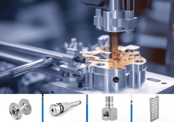
Aerospace parts are rarely made with one process alone. CNC milling creates prismatic features, pockets, slots, and mounting faces. CNC turning produces shafts, bushings, sleeves, and threaded diameters with good concentricity. Multi-axis machining reaches features on several sides and angled surfaces. Secondary operations such as deburring, cleaning, surface treatments, and inspection complete the part.
Four-axis and five-axis machining can help when features must hold a relationship to one another. Completing more faces in fewer setups reduces the number of times the part is clamped and re-referenced, which lowers handling risk and the accumulation of setup error. Fewer setups also make it easier to show that a feature relationship was produced in one controlled sequence.
Our equipment base is organized by process. The table below lists the listed precision for each machining category, drawn from our current equipment inventory.
| Process | Equipment | Qty | Listed precision | Typical components |
|---|---|---|---|---|
| CNC Milling | 3-Axis CNC Machining Centers | 25 | ±0.01 mm | Brackets, housings, mounting plates |
| CNC Milling | 4-Axis CNC Machining Center | 1 | ±0.01 mm | Multi-sided machined components |
| CNC Milling | 5-Axis CNC machines | 8 | ±0.01 mm | Complex profiles and multi-sided parts |
| CNC Turning | CNC Lathes | 43 | ±0.01 mm | Shafts, sleeves, bushings, turned parts |
| Turn-Mill Machining | CNC Turn-Mill Machines | 15 | ±0.01 mm | Components combining turning and milling features |
| Swiss-Type Machining | 5-Axis, 6-Axis, and other Swiss-type lathes | 10 | ±0.01 mm | Small precision and slender components |
| Automatic Turning | Automatic Lathes | 30 | ±0.02 mm | Pins, small turned parts, precision connectors |
| Screw Machining | Screw Machines | 20 | ±0.05 mm | Screws and threaded fasteners |
The best process depends on part geometry, material, quantity, and the evidence the customer requires. A slender shaft is usually a turning job first. A multi-faced housing with angled ports may be better on a multi-axis machining center. A small connector with fine diameters may suit Swiss-type machining. Batch size also matters, since setup time weighs more heavily on short runs.
Design for manufacturability checks
Before a drawing reaches the shop floor, we look for features that will be expensive or unreliable to produce as drawn. The most useful checks are simple:
Accessible features
Can the cutter physically reach each feature without interference from the part or fixture?
Tool reach
Deep pockets and long bores need tool lengths that remain rigid enough to hold the required size and finish.
Wall thickness
Very thin walls distort under clamping and cutting, so wall thickness should be balanced against stiffness needs.
Internal radii
Sharp internal corners force small tools or extra operations; reasonable radii keep the process stable.
Realistic tolerances
Each tight callout should be justified by function, not habit.
Quality Requirements and Standards
A documented quality management system is the foundation for consistent production. It defines how work is planned, how processes are approved, how records are controlled, and how problems are contained and corrected. Without that structure, a good first part does not reliably predict the hundredth.
AS9100 is the quality management standard widely used across aerospace supply chains. It is a system-level standard: it describes how an organization runs its quality processes. It is not a certificate that any individual part conforms to its drawing. Part-level acceptance still depends on inspection against the drawing and the acceptance criteria. We operate under a quality management system certified to AS9100D, subject to its valid certification scope, alongside ISO 9001 and ISO 13485.
Important distinction
A system certificate tells you how a supplier is managed. Part acceptance tells you whether the parts you received meet the drawing. Ask for both.
Customer, regulatory, and program-specific requirements can add controls beyond a general certification. A specific customer may require particular inspection methods, special process approvals, or records retained for a defined period. These requirements should be confirmed for each program rather than assumed from the supplier's certificate.
First Article Inspection and AS9102
First Article Inspection (FAI) verifies that the production process can make a part that meets the drawing. It is a proof of process, not just a check of one piece. A first article is typically produced with the intended materials, tooling, and setups, and then fully measured against the drawing.
AS9102 defines the First Article Inspection Report (FAIR) format. A FAIR records dimensional results and the relevant material or process evidence required for the part. Requirements for when an FAI is triggered, such as a new part, a design change, or a process change, should be confirmed for each program or customer before production begins.
FAI workflow
-
1
Confirm the drawing and FAI trigger
Verify revision, notes, and whether the program requires a full or partial FAI.
-
2
Produce the first article with the planned process
Use the intended material, setups, tooling, and work instructions.
-
3
Measure every required characteristic
Record dimensional and GD&T results, plus material and special process evidence as applicable.
-
4
Compile the FAIR and review it
Check results against the drawing and acceptance criteria before the customer receives the report.
Process Control and Production Consistency
Repeatability across production runs comes from controlled process details. Approved processes define how a part is made. Work instructions give operators the steps, offsets, and checks. Calibrated gauges and instruments keep measurements trustworthy. Revision control makes sure the shop works from the current drawing and not an old printout.
Approved processes
Documented methods for each part family and operation.
Calibration
Gauges and measuring instruments kept in a controlled calibration cycle.
Revision control
Only current drawings and instructions are issued to the floor.
Nonconformance handling
Suspect parts are segregated, dispositioned, and the cause is recorded.
Process monitoring catches drift before it becomes scrap. Trends in measured dimensions, tool life, and probe data show when a process is moving toward its limit. Corrective action then addresses the root cause, whether that is a worn fixture, a tool offset habit, or a missing instruction, and the change is verified on subsequent parts.
Digital traceability and controlled inspection records make this much easier to demonstrate. When each part can be linked to its material lot, program, operator, machine, inspection results, and drawing revision, audit questions are answered from records rather than memory.
Inspection and Verification of Aerospace Parts
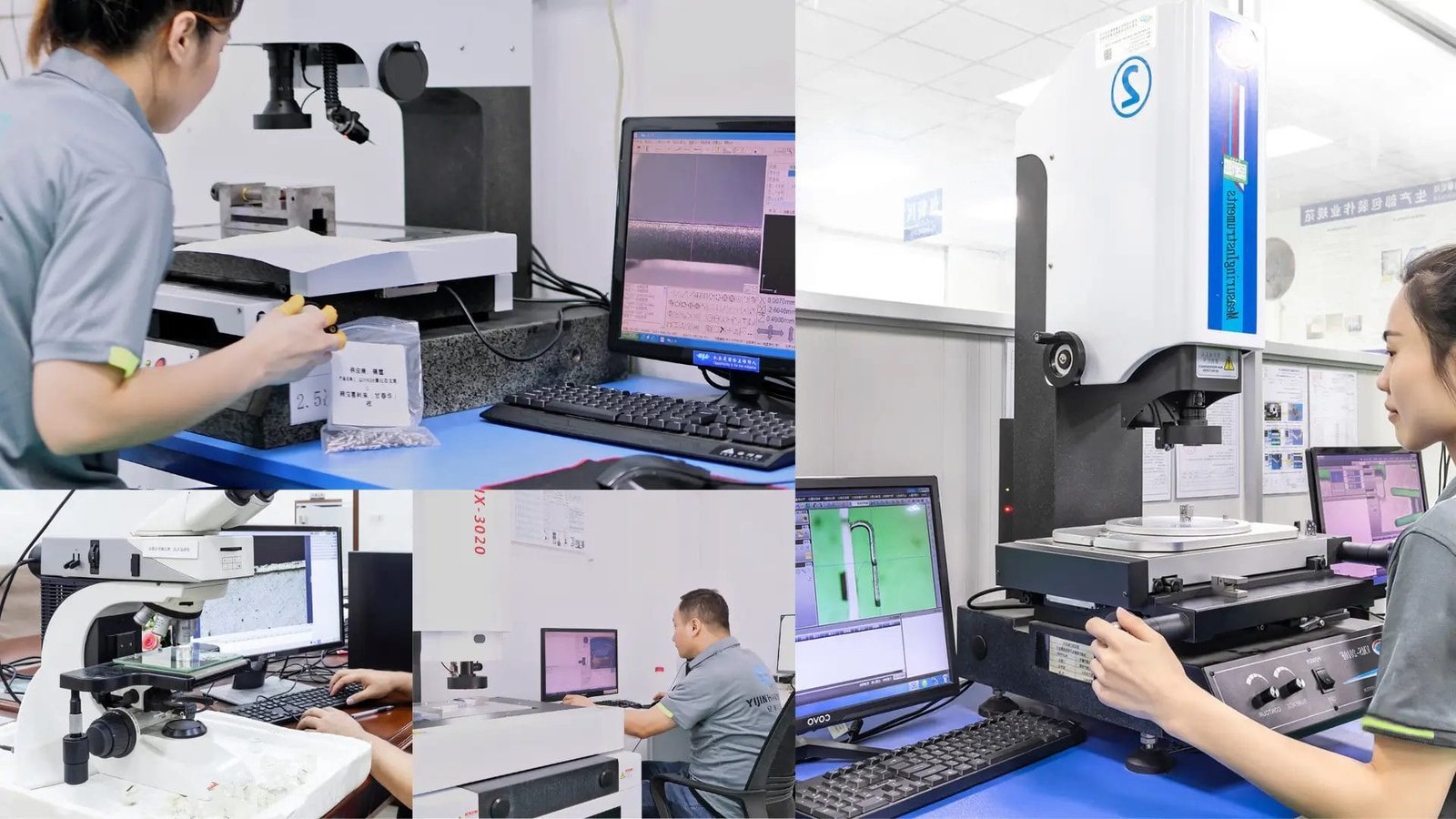
An inspection plan should be matched to the drawing characteristics and their risk. A critical hole position that controls assembly deserves a coordinate measurement with documented results. A cosmetic radius may only need a visual check against a gauge. The plan should list each characteristic, the method, the sample size, and the record it produces. For terminology, see ISO 9001 overview.
Common tools and methods include:
Calibrated gauges and micrometers
Pin gauges, thread gauges, height gauges, and calipers for routine and in-process dimensions.
Coordinate measuring machine (CMM)
3D dimensional and geometric verification of datum-referenced features and GD&T callouts.
Optical measuring systems
2D vision measurement of profiles, hole positions, and small dimensions without contact.
Surface roughness and hardness testing
Surface roughness testers and Rockwell hardness testers verify finish and material condition when specified.
In-process checks, final inspection, and GD&T verification
In-process checks catch problems while they are still cheap to fix, which is why critical features are often measured between operations. Final inspection then verifies the finished part against the drawing. For GD&T, the measurement must follow the datum reference frame named on the drawing; a measurement taken from a convenient surface may pass while the real requirement fails.
Every inspection result should be traceable to the applicable drawing revision and its acceptance criteria. A record that does not name the revision it was measured against cannot prove conformance to the current design.
Surface Finish, Treatments, and Special Processes
Surface roughness is a different requirement from a dimensional tolerance. A hole can be the right diameter and still have a finish too rough for a sealing or bearing surface. Roughness is specified separately, measured with a surface roughness tester, and controlled through tool selection, feeds, and finishing passes.
Post-machining treatments are often specified in the drawing. Depending on the program, these may include anodizing, passivation, coatings, or heat treatment. Each one changes the part in some way: coatings add thickness, anodizing can alter the size of threaded or close-fit features, and heat treatment can move dimensions. Coating thickness can be verified with a coating thickness gauge where specified.
Special processes
Special processes and their records must meet the applicable customer or program requirements. Confirm the approved source for each treatment and what certificates or test reports must accompany the parts before the purchase order is released.
Common Aerospace Machining Challenges
Most aerospace machining problems fall into a few familiar categories. Distortion appears when internal stress is released during material removal or when clamping forces bend a thin section. Burrs can hide at intersecting holes and edges, and they must be removed without damaging the feature. Thin-wall deformation makes it hard to hold flatness and size. Tool wear shifts dimensions gradually, and maintaining accuracy across complex features requires attention through the whole run, not just at the first part.
Reduce risk through material
Choose an alloy and stock condition that machines predictably for the design, and plan stress relief where distortion is expected.
Reduce risk through workholding
Support thin areas, distribute clamping force, and verify fixture location before committing to a full batch.
Reduce risk through toolpaths
Balanced roughing and finishing passes limit heat and deflection, and keep the tool engaged evenly.
Reduce risk through inspection
Match the inspection strategy to the features that drift most, and measure them often enough to see the trend.
Resolve before production
Drawing ambiguities cost more after the first chip is cut. Unclear datums, conflicting notes, missing thread specifications, or unspecified finish callouts should be resolved with the customer before production starts. A short written clarification is far cheaper than a scrapped batch.
Cost, Lead Time, and Tolerance Trade-Offs
Tighter tolerances increase machining time, inspection effort, and documentation requirements. Each additional critical feature may need its own tooling strategy, a dedicated in-process check, and a line on the inspection report. Multiply that across a part with dozens of features and the cost difference becomes significant.
The practical answer is to apply tolerances only where function requires them. Loose, well-chosen tolerances on non-critical features let the shop focus its capability on the few features that truly control fit and performance. That approach usually produces better parts, not just cheaper ones.
Factors that affect lead time
Material availability
Specified alloys and certified stock may need to be sourced before machining can begin.
Process approvals
New or changed processes may require customer approval before parts ship.
Special treatments
Anodizing, passivation, coatings, and heat treatment add scheduling steps and external dependencies.
First Article Inspection
FAI must be produced, measured, and reviewed before the production release, so it belongs in the schedule from day one.
How to Evaluate an Aerospace CNC Machining Supplier
A supplier should be judged on evidence, not claims. Start with relevant part and material experience: has the shop machined similar geometries in similar alloys? Then review process capability, quality systems, and inspection resources, and confirm that they fit the characteristics on your drawing.
Supplier review checklist
-
1
Traceability
Can the supplier link a part to its material lot, operator, machine, and inspection record?
-
2
Subcontracted special processes
Which treatments are done in-house, and which external sources are approved and documented?
-
3
Change control
How are tooling, process, material, and drawing changes reviewed and communicated before they affect parts?
-
4
Nonconformance management
How are suspect parts contained, reported, and corrected, and how is customer notification handled?
-
5
Capacity for prototype and production
Can the same process controls scale from development parts to repeat production runs?
Review sample documentation before awarding work. A representative inspection report, material certificate, and traceability record will tell you more than a capability sheet. Confirm that the supplier's quality certification scope covers the work you are placing, and that the records match what your program requires.
Early technical discussion is the most valuable step. Talk through the drawing, the critical features, the datum scheme, and the acceptance requirements before quoting. Suppliers who ask good questions about function and fit are usually the ones who will hold the part on the first run.
Frequently Asked Questions
What tolerances can aerospace CNC machining achieve?
Achievable tolerances depend on the feature, material, geometry, process, and inspection method. Our listed precision for milling and turning equipment is ±0.01 mm, but a specific feature should be quoted against its own geometry and material.
Does every aerospace part need ±0.001-inch tolerances?
No. Tolerances should reflect functional and drawing requirements. Applying the tightest band everywhere raises cost and scrap risk without improving function on non-critical features.
What is the difference between AS9100 and AS9102?
AS9100 is a quality management system standard that describes how an aerospace organization manages its processes. AS9102 is a First Article Inspection standard that defines how the FAI report is structured and what it records for a specific part.
What does a First Article Inspection Report include?
It summarizes dimensional results against the drawing and includes the supporting material and process evidence required by the applicable order or program.
Which materials are commonly used for aerospace CNC parts?
Aluminum, titanium, nickel alloys, and stainless steels are common families. The specific material is determined by the design and the approved specification.
How are aerospace CNC parts inspected?
Inspection covers dimensional, geometric, surface, material, and documentation checks as applicable, using gauges, CMMs, optical measurement, and surface testing matched to the drawing.
What documentation should accompany an aerospace machined part?
Required records depend on the drawing, purchase order, customer, and program. Confirm the list of certificates, inspection reports, and traceability records before production starts.
Can one supplier support both prototype and production parts?
It can, but the supplier should confirm process control, capacity, and qualification requirements for each stage, since prototype and production runs may trigger different approvals.
Start the conversation
Send us your drawing for a technical review
Share your engineering drawings, material specifications, critical features, and documentation requirements. Our team will review the datum scheme, tolerances, and inspection plan with you before quoting, so the requirements are clear from the start.
Request a quotationFor aerospace-scope work, We operate under AS9100D/EN9100 (CN044900) together with ISO 9001 (HIC241500). ISO 13485 (04526MDQ00014R100), IATF 16949 (0565487), and ISO 14001 (HIC241501) are also held within each certificate’s stated scope—confirm applicability per project.