Precision Inspection Guide
CMM Inspection for CNC Parts: What Buyers Should Expect in Quality Reports
A CMM report is only as useful as the evidence behind it. This guide explains what a credible coordinate measuring machine report should contain, how to read datums, tolerances, and measurement tables, and what to request in your RFQ before machining starts.
"A green PASS stamp tells you someone decided the part was good. A well-built CMM report lets you check that decision yourself against the drawing."
Quick Answer: What a Good CMM Report Should Prove
When we review a CMM report for a CNC part, we look for five things. If any one of them is missing, the report can still be useful as a record, but it cannot fully support an acceptance decision.
- 1 Traceability: the part number, drawing revision, and serial or lot are clearly tied to the report.
- 2 Datum-referenced results: features are measured from the datum reference frame the drawing specifies.
- 3 Actual values against nominal and tolerance: every measured value is shown next to its nominal and limits, not just a result flag.
- 4 Pass/fail with uncertainty context: results near a limit are interpreted with the measurement uncertainty in mind.
- 5 Sampling scope: the report states how many parts were measured and which features were covered.
A report that simply says PASS cannot be checked. A useful report can be laid next to the drawing, feature by feature, and verified by your own team or your incoming inspector.
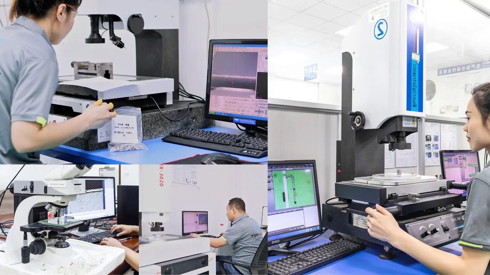
What Is CMM Inspection?
A coordinate measuring machine (CMM) is a metrology system that uses a touch probe, or sometimes a non-contact sensor, to record the position of points on a physical part within a defined three-dimensional coordinate system. The software then calculates features such as diameters, planes, and positions from those points and compares them with nominal values from CAD or a 2D drawing.
In practice, this means a CMM answers a specific question: does this physical part match the geometry the designer defined? That is different from asking whether the material is correct or whether the surface feels right to the touch.
Scope Note
CMM inspection measures geometry: dimensions, form, orientation, and position. It does not measure material properties, hardness, or surface finish by default. Those need separate reports, covered later in this guide.
Shop context
YJCNC machining context
- YJCNC is a mid/small CNC shop serving English-language B2B buyers with no MOQ.
- Sample and production lots often complete in about 3–7 days when material is available.
- DFM review from drawings is offered before locking process plans; certificates include ISO 9001, ISO 14001, AS9100D, ISO 13485, and IATF 16949 within scope.
What CMM Inspection Can Measure
A CMM covers a broad range of geometric features. The practical question is which ones are worth measuring on the machine, and which ones need a different tool.
Dimensions and Features
Linear and angular dimensions, hole diameters, slot widths, step heights, and distances between features. Threads can be checked when the right probes or gauges are used.
Form and Position Tolerances
Flatness, position, perpendicularity, coaxiality, and runout are the GD&T characteristics where a CMM adds the most value, because they depend on datum relationships.
Complex Surfaces and Contours
Scanned or probed surfaces can be compared to the CAD nominal, producing deviation data that shows where material sits above or below the design surface.
Where Other Methods Are Needed
Surface roughness, hardness, and internal material defects usually require a profilometer, hardness tester, or NDT method rather than a CMM.
When Should Buyers Request CMM Inspection?
Not every CNC part needs a full CMM program. Over-specifying inspection adds cost and lead time without reducing risk. Under-specifying it can let a tolerance problem reach your assembly line. The table below is a practical starting point.
| Situation | Recommended Inspection |
|---|---|
| Tight tolerances, for example under ±0.02 mm | CMM with full dimensional report |
| GD&T-driven features such as position, runout, or perpendicularity | CMM with datum-referenced results |
| Aerospace, medical, automotive, or safety-critical parts | CMM plus first article and documented traceability |
| Non-critical, loose-tolerance features | Calipers, micrometers, or gauges may be sufficient |
Decide Early
Decide on the inspection level before quotation, not after machining starts. Changing the inspection scope mid-run means re-checking parts already made, and that can cost more than the inspection itself.
Which Drawing Requirements Must Be Defined Before CMM?
A CMM program can only check what the drawing defines. Before we write a measurement program, these inputs need to be settled.
Revision, Units, and Default Standards
The drawing revision, unit system, and default tolerance standard, such as ISO 2768 or ASME Y14.5, must be stated on the drawing.
Critical-to-Function (CTF) Dimensions
Identify the features that govern fit or function so they receive full measurement rather than sampling.
Datum Scheme and Modifiers
The primary, secondary, and tertiary datums must be defined, along with material condition modifiers such as MMC, LMC, or RFS where they apply.
Sampling Expectation
Specify whether you need all features measured, first article only, or periodic checks during the run.
How Does CMM Fit Into the Manufacturing Workflow?
CMM inspection is most valuable when it is placed at the right points in the process, not only at the end.
-
1
First Article
Full CMM measurement of the first production part against the complete drawing, before the batch is released.
-
2
In-Process Checks
Targeted checks of critical features at set intervals, using gauges or on-machine probing where practical.
-
3
Final Inspection
Verification of the defined sample or features before shipment, with the report issued against the batch.
Measuring the first part on the CMM is the cheapest insurance in the entire run. If a datum is set incorrectly or a tool offset drifts, the first article catches it while only a few parts are affected. Waiting until the end of the batch can turn a single fixture error into a rework job across hundreds of pieces.
On-machine probing and in-process gauging are useful complements. They shorten feedback loops on the shop floor. They do not replace a calibrated CMM for final geometric verification of the features that matter most.
Anatomy of a CMM Inspection Report
A typical CMM report has several sections. Read them in order, because each one depends on the one before it.
Traceability Block
This block should list the part number, drawing number and revision, serial or lot number, material, operator, date, and CMM machine ID. Verify this block first. A report that cannot be tied to the exact drawing revision has limited value, no matter how precise the numbers look.
Typical traceability fields
- Part number
- Matches the purchase order
- Drawing and revision
- Current released revision
- Serial or lot
- Identifies the measured part or batch
- Material
- Matches the drawing note
- Operator and date
- Who measured and when
- CMM machine ID
- Links to calibration records
Measurement Summary
The summary gives the overall pass/fail count, the number of features measured, and the out-of-tolerance items highlighted for quick review. Use it as a map, not as the decision itself. Check that the feature count matches the drawing; a summary that counts fewer features than the drawing defines means some features were not measured.
Measurement Table
The measurement table is the core of the report. Each row should carry a feature ID that matches a balloon or callout on the drawing, the nominal value, upper and lower tolerance limits, the actual measured value, the deviation, and the result.
| Feature | Nominal (mm) | Tolerance (mm) | Actual (mm) | Deviation | Result |
|---|---|---|---|---|---|
| A1 Step length | 25.00 | +0.05 / -0.05 | 25.04 | +0.04 | PASS |
| B2 Bore diameter | 12.00 | +0.02 / 0.00 | 12.027 | +0.027 | FAIL |
| C3 Position (MMC, Ø0.05 A) | Basic | Ø0.05 | Ø0.031 | Within | PASS |
Watch for entries that look too neat. Identical actual values across several parts, a list that skips feature IDs, or values rounded to the same decimal place as the nominal every time can indicate a template that was filled in rather than measured. Ask for the raw coordinate data when a feature is critical.
Quick spot-check list
Identical values across parts from different serials
Missing feature IDs compared with the drawing callouts
Rounded results that hide the resolution of the measurement
Unit mismatch between the report and the drawing
Datum References and Alignment
Position and runout results depend entirely on how the datum reference frame (DRF) is built. The software aligns the part to the datums, and small differences in that alignment can shift every position result. A part aligned to a different datum sequence can pass in one report and fail in another, even though the physical part did not change.
Warning
If the report shows a datum shift, a changed datum order, or datums that do not match the drawing, do not approve the GD&T results until the supplier explains and corrects the alignment.
Graphical Output and Color Maps
Deviation plots and scan overlays show where a surface sits relative to nominal. They are very useful for spotting a warped face, a tilted boss, or a contour that drifted across a batch. They confirm the spatial pattern of deviation. They do not, by themselves, confirm that every tolerance on the drawing was checked, and a colorful map can hide a single out-of-tolerance hole in a sea of green.
Measurement Uncertainty and Environment
A credible report states a measurement uncertainty value or refers to how it was estimated. Temperature matters: metrology is usually referenced to 20 °C, and parts need time to stabilize to room temperature before measurement. A part that has just come off a machine can still be warm, and its dimensions will not match the reference condition.
Results near a limit deserve special attention. A value that is inside the tolerance band by less than the measurement uncertainty is not a clean pass. We discuss how to handle that in the next section.
How to Read a CMM Report Step by Step
If you are new to CMM reports, follow this sequence every time. It takes a few minutes per report and catches most problems early.
-
1
Start with traceability
Confirm the part number, revision, and serial or lot match your order and your drawing.
-
2
Check the datums
Verify that the datum scheme in the report matches the drawing before reading any GD&T result.
-
3
Review tolerance-critical features
Go to the CTF features first and read the actual values, not just the result flags.
-
4
Read the full table
Scan every row for missing IDs, suspicious patterns, and near-limit values.
-
5
Check uncertainty and environment
Look at the uncertainty statement and temperature notes for any value close to a limit.
Worked Example: A Simple Diameter Check
Take a length feature with a nominal of 25.00 mm and a tolerance of ±0.05 mm. The acceptable range is therefore 24.95 mm to 25.05 mm. If the measured value is 25.04 mm, the deviation is +0.04 mm, which is inside the limit. The result is a pass.
Now suppose the measured value is 25.04 mm but the measurement uncertainty for that feature is ±0.02 mm. The true value could be anywhere from 25.02 mm to 25.06 mm, and part of that range sits outside the upper limit. A careful reviewer would ask for guard-banding. Guard-banding means tightening the internal acceptance limit so that a part is accepted only when the whole uncertainty interval stays within the drawing tolerance. Here, that would move the effective upper limit to about 25.03 mm, and the 25.04 mm part would be flagged for disposition rather than accepted automatically.
Interpretation Tip
The guard-band approach is a decision rule, so the supplier and buyer should agree on it in advance. Ask which rule was used when a result sits within the uncertainty of a limit.
Interpreting Position with Material Condition Modifiers
With MMC (maximum material condition) applied to a position tolerance, the allowable position error grows as the feature moves away from its maximum material size. A hole drawn at its smallest allowed diameter gets the smallest bonus tolerance; a hole that has been machined larger gets more. The report should show the actual size of the feature alongside the position result, so you can calculate the bonus tolerance yourself. If the report shows only the position value and not the feature size, ask for both.
Beginner Walkthrough
If you only remember one thing, remember this: match the report to the drawing feature by feature. Each row should correspond to a callout you can point to. If you can do that for the critical features, you can trust the report far more than any summary page.
How to Calculate and Understand CMM Accuracy
CMM accuracy is one of the most misunderstood topics in inspection reports. There are two different ideas that often get blurred together.
Machine Accuracy
Volumetric performance of the machine itself, typically characterized under ISO 10360. It describes how the machine performs across its measuring volume under defined test conditions.
Measurement Uncertainty
The uncertainty for a specific part, feature, fixture, probe, and setup. This is the number that matters when deciding whether a result near a limit is acceptable.
Machine accuracy is often written in a form such as (1.5 + L/300) µm, where L is the measured length in millimeters. For a 300 mm measurement, the term L/300 equals 1, so the expression gives roughly 2.5 µm. That figure is a machine specification under test conditions. It is one input to the uncertainty budget, not the final answer for your part.
A full uncertainty estimate also considers probe qualification, the form error of the feature, fixturing, temperature, part stabilization, operator technique, and the sampling strategy used for the feature. For a feature that is measured with a few touch points on a rough surface, the uncertainty can be much larger than the machine specification alone suggests.
Important Distinction
A calibration certificate for the CMM confirms the machine was checked at a point in time. It does not automatically guarantee the result for a specific part. Ask for the uncertainty estimate for the critical features, not only the machine certificate.
CMM Report vs. First Article Inspection (FAI) vs. Other Documents
Buyers often receive several documents for the same order and assume they cover the same ground. They do not. Each answers a different question.
CMM Inspection Report
Dimensional evidence for a specific set of parts, showing measured values for the features that were selected for measurement.
First Article Inspection Report
A full-drawing verification of initial production, typically structured per AS9102 or a similar standard. Features are balloon-referenced to the drawing so every characteristic is accounted for. An FAI is broader than a single CMM run, because it confirms that the process can produce the whole drawing.
Material Certificate
Chemical and mechanical properties tied to a heat or lot number. It proves what the material is, not how the machined geometry turned out.
Surface Finish Report
Roughness measurements and, where applicable, plating or coating certifications. Our surface roughness tester and coating thickness gauge support this type of verification when it is specified.
Certificate of Conformance (CoC)
A supplier statement that the parts comply with the specified requirements. A CoC is useful for the paperwork trail, but it is weaker than measured data because it states compliance rather than showing the evidence.
Comparison Table
| Document | Purpose | Scope | When Required |
|---|---|---|---|
| CMM Inspection Report | Dimensional evidence | Selected features on sampled parts | Tight tolerances, GD&T, critical parts |
| First Article Inspection | Confirms the process can make the full drawing | Every drawing characteristic, balloon-referenced | New parts, new processes, or setup changes |
| Material Certificate | Proves material composition and properties | Heat or lot of stock material | Material-controlled or safety-critical parts |
| Surface Finish Report | Roughness and coating verification | Specified surfaces | Surfaces with roughness or coating callouts |
| Certificate of Conformance | Supplier compliance statement | Whole order, as a declaration | Standard paperwork for most orders |
Fixtures, Sampling, and Batch Acceptance
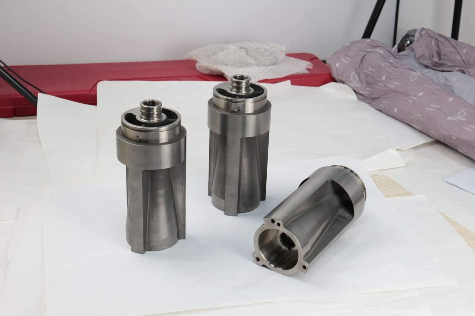
Fixturing affects the result as much as the probe does. Flexible or thin-walled parts can deflect under clamping or probing force, so the measured geometry may reflect the restraint rather than the part in free state. A good report or inspection plan says how the part was held and whether the fixture was designed to avoid distortion.
Sampling is the second question. A passing part does not prove the whole batch is good. Acceptance plans, such as those based on an AQL, define how many parts are inspected and what defect level is acceptable across the lot. A fixed sample size works in a similar way, with a clear accept/reject rule.
Define the sample in writing
State the sample size, selection method, and acceptance rule in the RFQ or quality plan.
Request SPC data for high-volume runs
Statistical process control charts show whether a dimension is drifting over time, which a single passing part cannot reveal.
Tolerance Stack-Up and Thermal Effects
Every feature can pass its own tolerance and the assembly can still fail. When several features in a chain each sit near the edge of their band, their combined error can exceed the clearance a mating part needs. A report that shows each feature as a pass does not show the stack. For assemblies, ask the supplier to check the critical chain as a unit or to share the individual values so your engineers can run the stack calculation.
Thermal expansion is the other hidden variable. Aluminum expands more than steel for the same temperature change, so an aluminum part measured just after machining can read differently from the same part after it has stabilized. Steel parts are less sensitive but still need time to reach the reference temperature. Stabilization time before measurement should be recorded in the report or inspection plan.
Practical Note
If your assembly has a tight fit between aluminum and steel parts, specify both the reference temperature and the stabilization step in the RFQ. Otherwise, two reports for the same lot can disagree for reasons unrelated to workmanship.
Common CMM Report Mistakes Buyers Should Avoid
These are the errors we see most often when customers review reports from any supplier, including ourselves in early cases where requirements were unclear.
Checking only the final PASS
The overall result hides which features were measured and how close they came to limits.
Ignoring revision and unit mismatch
A report written against an older drawing, or in inches for a metric drawing, is not evidence for the current part.
Accepting datum shifts without review
A changed datum order can flip position results. It needs an explanation before approval.
Treating one part as proof for the batch
One measured part supports only that part unless the sampling plan says otherwise.
Assuming CMM is the best tool for everything
Roughness, hardness, and material properties need their own methods and reports.
Ignoring uncertainty near limits
A value inside the band by less than its uncertainty needs a documented decision rule.
Confusing calibration with capability
A current machine calibration does not prove a specific part measurement is reliable.
Requesting CMM too late
Adding inspection after machining starts often means re-checking parts already made.
Cost vs. Project Risk: Deciding How Much Inspection to Buy
Inspection is a cost line, but it should be compared against what a defect would cost you: scrap, rework, line stoppage, a field failure, or a customer audit finding. A part that goes into a medical or aerospace assembly carries a different risk profile than a bracket with generous tolerances. Match the inspection package to that risk rather than buying the largest package by default.
Tier 1
Basic Dimensional
Calipers, micrometers, and gauges for non-critical features with loose tolerances.
Tier 2
Full CMM with GD&T
Datum-referenced measurement of tight and GD&T-driven features with a documented report.
Tier 3
Full FAI with SPC
Balloon-referenced first article, plus statistical data across the production run.
What to Include in a CMM Inspection RFQ
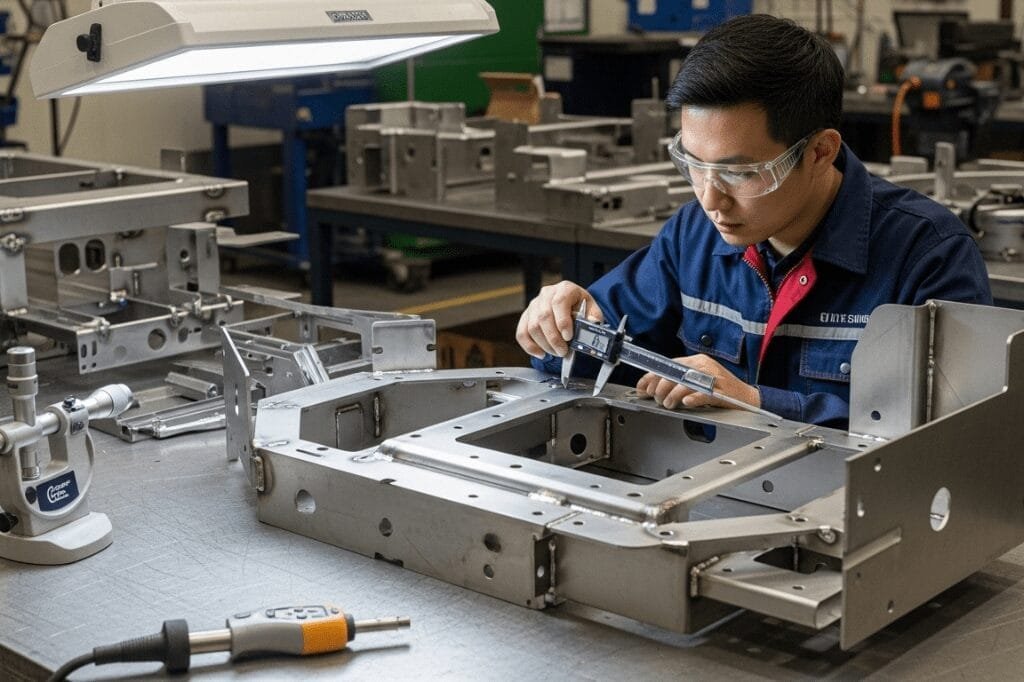
A clear RFQ prevents most of the disputes described above. Use this checklist when you request a quotation for CNC parts that need CMM reporting.
- 1
Drawing revision
Name the exact revision the report must reference.
- 2
CTF features
List the features that need full measurement with balloons or callouts.
- 3
Required GD&T characteristics
Specify the datum scheme and any MMC, LMC, or RFS conditions.
- 4
Sampling level
State first article only, fixed sample, AQL plan, or full inspection.
- 5
Report format
PDF for review, Excel for raw data, or STEP-based or digital PMI data for direct CAD comparison. For instrument types and terminology, see Coordinate-measuring machine.
- 6
Acceptance criteria
Define the decision rule for results near limits, including guard-banding.
- 7
Supporting documents
Indicate whether you need FAI, material certificates, surface finish reports, or a CoC.
Trends in Digital Inspection Reporting
Inspection reporting is moving toward data that can be checked automatically rather than read by eye.
Model-Based Definition and STEP AP242
Model-based definition (MBD) with embedded PMI in STEP AP242 lets the CAD model carry the tolerances, so a report can be compared directly with the design data rather than retyped from a PDF.
Automated Reporting and Inline Probing
Automated report generation and probing integrated with production shorten turnaround and reduce transcription errors.
Digital Sharing and QMS Traceability
Reports shared through quality management platforms keep the link between part, revision, and measurement record intact over the life of the part.
These tools help most when the inputs are already clean. Digital reporting cannot fix an undefined datum scheme.
How to Prepare CNC Files for Reliable Inspection
Good inspection starts with good files. We recommend sending the native CAD model together with a fully dimensioned 2D drawing that carries the GD&T. The model supports program creation and nominal comparison; the drawing defines the requirements that govern acceptance, including geometric dimensioning and tolerancing.
- Mark datums and critical features clearly on the drawing.
- State the default tolerance standard in the title block or general notes.
- Confirm the revision on the model and the drawing match.
Red Flags in Supplier CMM Reports
Some signs suggest a report needs a closer look before you rely on it.
Escalate if you see
- Missing traceability or no revision on the report
- Generic templates with no part-specific values
- Identical values across different serial numbers
- No datum definition for GD&T results
- Refusal to share raw data for critical features
Frequently Asked Questions
What is a CMM in quality inspection?
A CMM is a coordinate measuring machine that probes a part and compares its measured geometry with CAD or drawing values. In CNC work, it verifies dimensions, form, and position against the drawing.
What is CNC quality inspection?
It covers incoming checks of material, in-process checks during machining, and final inspection before shipment. Each stage produces records such as gauge checks, CMM reports, FAI reports, and certificates.
How do I interpret a CMM report?
Work in sequence: traceability, datums, critical features, the full table, then uncertainty and environment. The full method is described in the step-by-step section above.
How do I calculate CMM accuracy?
Machine accuracy is a volumetric specification, often written like (1.5 + L/300) µm. Measurement uncertainty for a specific feature must be estimated separately, including probe, fixture, temperature, and form error.
Is CMM inspection necessary for every CNC part?
No. It is most valuable for tight tolerances, GD&T features, and safety-critical or regulated parts. Loose-tolerance features are often checked adequately with gauges and calipers.
What is the difference between a CMM report and an FAI report?
A CMM report gives measured values for selected features on sampled parts. An FAI report verifies the full drawing for initial production, usually with balloon-referenced features.
Can a CMM measure threads and surface roughness?
Threads can be verified with specialized probes or gauges such as thread ring and plug gauges. Surface roughness typically requires a profilometer or surface roughness tester.
Why can two CMM reports differ for the same part?
Common causes include fixturing, datum alignment, probe qualification, temperature and stabilization, and operator technique. Comparing reports is only meaningful when these conditions are recorded.
Does a passing CMM report prove the whole batch is good?
Not by itself. Acceptance depends on the sampling plan, the statistical behavior of the process, and whether the sample represents the lot. SPC data and a defined acceptance plan give that confidence.
Conclusion
A CMM report should give you traceable data, correct datum alignment, clear handling of uncertainty near limits, and documentation matched to the risk of the part. When those elements are present, you can verify the result yourself. When they are missing, a PASS stamp is only a claim. Further process detail lives under ISO 9001 quality system.
The best time to settle these details is before the first chip is cut. Define the critical features, the datum scheme, the sampling plan, and the report format together, and the inspection results will mean what you need them to mean.
Next Step
YJCNC’s quality and environmental systems include ISO 9001 (HIC241500), ISO 14001 (HIC241501), AS9100D/EN9100 (CN044900), ISO 13485 (04526MDQ00014R100), and IATF 16949 (0565487), each within its certified scope.
Review Your Inspection Requirements Before Requesting a Quote
Send us your drawing, the features you consider critical, and the report format you need. We will review the datum scheme, tolerance approach, and sampling level, then propose an inspection plan that matches the part before production begins. You can also reach our team directly at or info@yjcncmachining.com.
Request an Inspection Plan