YJCNC Engineering Guide
CNC Lathe Machining Guide: From Simple Turning to Complex Rotational Parts
Process notes from our CNC turning team—drawing review, routing, and inspection planning.
Understand how CNC lathes create accurate rotational features, when live tooling or mill-turn is useful, and what to consider when specifying tolerances and inspection for custom parts.
Quick Answer
Start with simple OD/ID turning, then add grooves/threads, then live tooling for cross-features—escalate to Swiss or full turn-mill only when geometry and volume require it.
CNC lathes excel at machining diameters, faces, grooves, and threads on rotational parts. The workpiece spins while a cutting tool removes material, making turning a natural choice for shafts, sleeves, bushings, pins, and other components built around a central axis. When a part also needs cross-holes, flats, or milled patterns, live tooling or a mill-turn process may reduce handling between operations.
We review the drawing, part geometry, tolerance scheme, and order requirements together to select a practical route—whether that is conventional CNC turning, automatic turning, Swiss-type machining, or turn-mill machining.
Shop context
Lathe complexity ladder
- Simple OD/ID turning covers pins, bushings, and stepped shafts; grooves and threads add standard second ops.
- Cross-holes, wrench flats, and milled pockets on a turned blank are where live tooling or a mill second-op earns its keep.
- We review drawings for single-setup turn-mill versus split routing before quoting—no MOQ for prototype or production lots.
Simple Turning Basics
Turning is often the most direct way to produce a concentric, round component. A CNC program coordinates spindle rotation, tool movement, and cutting conditions to shape the workpiece to the drawing. The details that look simple on a print—such as a shoulder, a short land, or a face-to-diameter relationship—still depend on a sound setup and clear datum choices. Further process detail lives under our CNC turning capability page.
What the lathe does
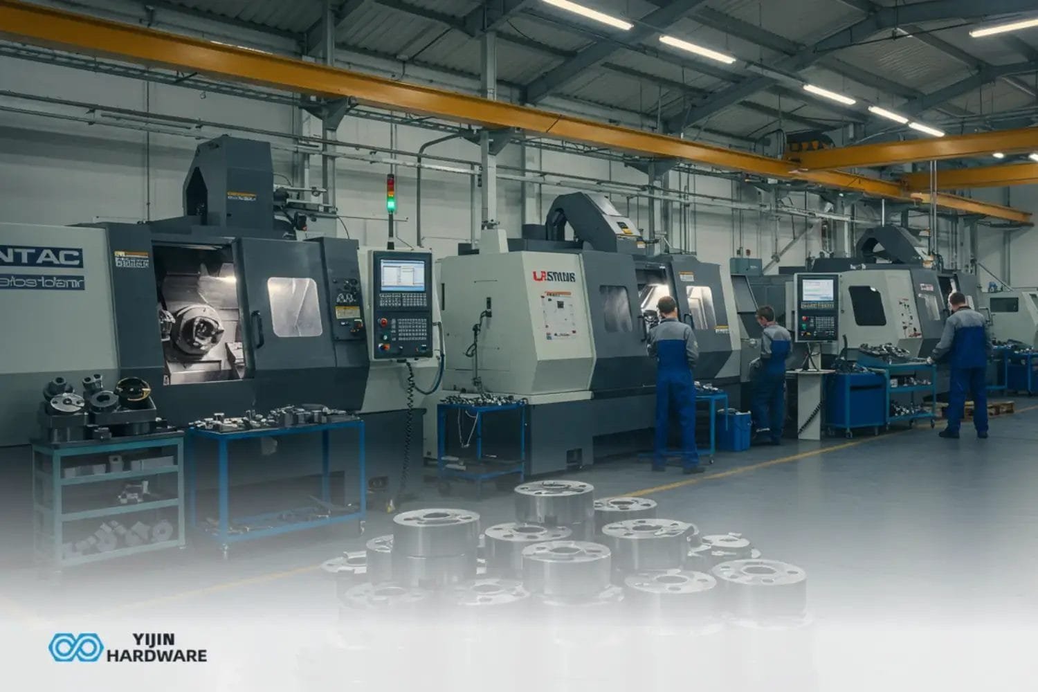
The spindle holds and rotates the material, while a stationary or programmed cutting tool advances along the part. Depending on the machine and setup, the work may be held in a chuck, collet, or other suitable workholding. Tool paths can control the outside diameter, inside diameter, face, and transitions between them.
Common turning operations
Facing and straight turning
Facing creates a flat end surface; straight turning brings an outside diameter to size. These operations commonly establish the part’s end reference and primary cylindrical surfaces.
Boring and drilling
Drilling creates an initial hole, while boring enlarges or refines an existing bore. Specify the bore diameter, depth, and any fit or finish requirements that matter to assembly.
Grooving and parting
Grooves can provide clearance, retain a ring, or define a seal feature. Parting separates a completed component from bar stock, so the end condition should be considered in the design.
Taper and contour turning
A programmed tool path can produce tapers, radii, and shaped profiles. Call out the dimensions or profile controls that define the functional surface.
Designing for turning
A drawing is easier to manufacture when important diameters, lengths, and relationships are dimensioned from consistent datums. For example, if a shaft’s bearing seats must align, identify the relevant datum axis and control the relationship between the seats rather than relying on unrelated dimensions alone.
Design note
Review narrow grooves, deep bores, long slender sections, and abrupt changes in diameter early. These features can affect tool access, workholding, deflection, and the sequence used to machine and inspect the part.
Complex Rotational Features
Rotational parts can contain more than a sequence of simple diameters. Multiple shoulders, reliefs, undercuts, bores, and thread forms may need to work together in an assembly. The challenge is not only producing each feature, but preserving their intended relationship through machining and inspection.
Profiles, shoulders, and grooves
For a stepped shaft, the shoulder position can be just as important as the diameter because it may locate a bearing, gear, or spacer. Use clear axial dimensions and indicate edge breaks, radii, and reliefs where they affect fit or function. If the part has a specified profile or surface transition, make its controlling dimension or geometric requirement explicit on the drawing.
Threads and bore features
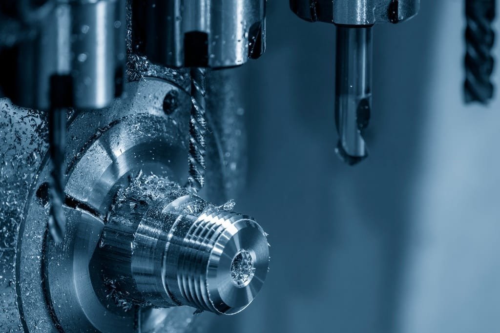
Thread callouts should identify the thread standard and size, along with any specified class, depth, or engagement requirement. For internal threads, include the usable thread depth and the bore or counterbore details needed for the mating component. Thread gauges can verify thread acceptance, but they do not replace inspection of other dimensions such as location, depth, or adjoining shoulders.
-
Define the functional thread
Include the required standard, size, class when applicable, and thread extent.
-
Show how the bore meets the face
Clarify chamfers, counterbores, and depth references where they affect assembly or tool access.
-
Prioritize critical relationships
Identify which features control alignment, sealing, retention, or a mating fit.
Live Tooling and Mill-Turn
A standard turning setup is ideal for axis-centered features. If the same component also requires features across its axis, a machine with live tooling or a turn-mill process may be appropriate. These capabilities allow turning and certain milling or drilling operations to be completed within a coordinated machining route, subject to the part geometry and machine setup. For terminology, see Lathe.
When live tooling helps
Live tooling is useful when a turned part needs features such as cross-holes, milled flats, slots, or patterns that are not concentric with the spindle axis. For a connector, for example, turning may establish its cylindrical body and thread while live tooling can produce a cross-hole or a wrench flat. Whether combining the operations is the right choice depends on access, tolerances, workholding, and the full production plan.
Choosing a process
We compare the drawing’s feature mix and part size with suitable turning, Swiss-type, and turn-mill options. Our listed equipment includes 43 CNC lathes and 15 CNC turn-mill machines, alongside automatic and Swiss-type lathes. That range helps us evaluate different geometries; it does not mean every part should be routed through a single process.
| Part requirement | Process to consider | Engineering question |
|---|---|---|
| Primarily concentric diameters, faces, and threads | CNC turning | Which diameters and axial relationships are function-critical? |
| Small or slender turned component | Automatic or Swiss-type machining, as suitable | What are the part length, diameter, feature access, and production needs? |
| Turned body plus cross-axis features | Live tooling or turn-mill machining | Can the required features be reached and referenced in a coordinated setup? |
| Complex multi-sided geometry | Evaluate turn-mill and milling operations | Which process sequence controls feature alignment and inspection? |
Tolerance and Inspection Notes
A tolerance should describe what the part needs to do, not simply make every dimension as tight as possible. Excessively restrictive requirements can increase manufacturing and inspection effort without improving function. We recommend identifying critical-to-fit or critical-to-performance features and making their datums and controls clear on the drawing.
| Shop parameter | Listed / verified figure | How to read it |
|---|---|---|
| CNC lathes | 43 machines; listed precision ±0.01 mm | From our equipment inventory (About). Listed precision is machine capability, not a blanket print guarantee. |
| Turn-mill machines | 15 machines; listed precision ±0.01 mm | Used when live tooling / combined features beat a second mill op. |
| Automatic lathes | 30 machines; listed precision ±0.02 mm | Favors smaller pins/connectors on longer runs. |
| Swiss-type lathes | 10 machines (4×5-axis + 2×6-axis + 4 other); listed precision ±0.01 mm | For slender / high-feature small-diameter work. |
| Gang-type CNC lathes | 7 machines; listed precision ±0.01 mm | Small shafts and precision connectors. |
| Surface roughness (Ra) | Verified when specified on the print (surface roughness tester on site) | We do not publish a single default Ra for all turned jobs—call out functional finishes on the drawing. |
| Order quantity | No MOQ | Prototype through production, subject to material and capacity. |
Figures above come from our published CNC equipment inventory. Feature-level tolerances, bar vs chucking, and finish still follow the drawing and DFM review.
Specifying tolerances
-
1
Start with the assembly function
Identify fits, bearing locations, sealing surfaces, and alignment requirements before assigning tight limits.
-
2
Choose useful datums
Reference dimensions to the surfaces or axis that locate the part in its real assembly.
-
3
Call out finish and geometry where needed
Specify surface roughness, concentricity-related controls, or other geometric requirements only where function requires them.
-
4
Align inspection with the drawing
Agree which dimensions and characteristics require verification, and how results should be documented.
Planning inspection
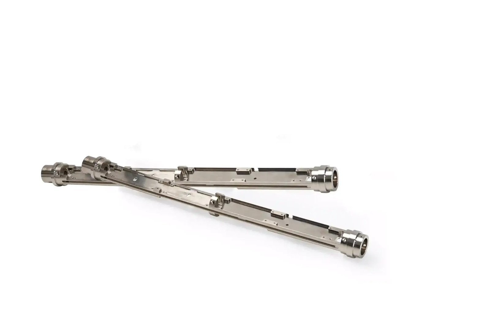
Inspection method should suit the feature. Micrometers and precision dimensional gauges can support checks on turned diameters; thread ring and plug gauges support external and internal thread inspection; optical measuring systems can assess profiles and hole positions. For three-dimensional or geometric requirements, a coordinate measuring machine may be appropriate. Our inspection resources also include height measurement, concentricity measurement, surface roughness testing, hardness testing, and coating thickness measurement.
Quality planning
We operate quality management systems certified to ISO 9001, ISO 13485, and AS9100D. ISO 14001 and IATF 16949 are also held within their certified scopes—confirm applicability during drawing review.
From simple turning to mill-turn — a practical ladder
Think of lathe work as a ladder. Step one is OD/ID turning and facing. Step two adds grooves, chamfers, and single-point or tap threads. Step three introduces live tooling or a second mill op for flats, hexes, and cross-holes. Step four is full turn-mill or Swiss for slender, high-feature parts.
| Ladder step | Typical features | Shop note |
|---|---|---|
| 1 — Simple turn | Steps, faces, basic bore | Fast quotes; bar-fed or chucked |
| 2 — Features of revolution | Grooves, threads, tapers | Watch runout callouts |
| 3 — Live tool / second op | Flats, cross-holes, slots | One chucking vs two ops trade-off |
| 4 — Complex rotational | Multi-axis contours, slender | Swiss or turn-mill discussion |
Inspection follows the ladder: micrometers and bore gauges cover steps 1–2; CMM or optical methods appear when true position of cross-features ties back to the turned axis. Certificates (ISO 9001, ISO 13485, and AS9100D as primary QMS; IATF or ISO 14001 when in scope) frame the documentation depth—not every commercial bushing needs an aerospace packet.
Example: an aluminum roller Ø50 × 120 mm with two bearings seats (±0.02 mm) and a milled keyway. We turn and finish the seats in soft jaws, then cut the keyway with live tooling so the keyway centerline stays tied to the seats without a second chucking. For terminology, see Turning.
FAQ
Bar feed or chucking—what changes for me as a buyer?
Bar feed favors longer runs of smaller diameters; chucking suits larger envelopes or near-net blanks. We pick based on diameter, length, and quantity—not a fixed rule.
Can you match a ground finish without grinding?
Sometimes with careful finish passes, but if the print truly needs grind-level roundness/Ra, we will say so rather than over-promise turning alone.
How early should live tooling be considered?
As soon as cross-features reference the turned axis. Waiting until after a pure-turning quote often causes re-quote churn.
Conclusion
CNC lathe machining ranges from straightforward diameter and face work to detailed rotational profiles and parts that combine turning with milled features. Good results begin with clear functional dimensions, sensible datums, and an inspection plan that reflects the drawing rather than treating every feature the same way. See also live tooling and turn-mill capability for practical context.
We support custom turning, turn-mill, and Swiss-type machining requirements for prototype development, repeat orders, and production runs, subject to project needs. Contact us to discuss your drawing and request a CNC machining quotation.
Project discussion
We operate under ISO 9001 (HIC241500), ISO 13485 (04526MDQ00014R100), and AS9100D/EN9100 (CN044900)—the same primary QMS set listed on our About page. We also hold ISO 14001 (HIC241501) and IATF 16949 (0565487); confirm which certificates apply to your drawing package and end-use before release.
Review your turned-part requirements with YJCNC
Share your drawing, quantities, and quality requirements. We will review the component geometry and discuss a suitable machining and inspection approach.