YJCNC Engineering Guide
CNC Machining Copper: Grades, Challenges & Design Tips
Copper is a demanding material to machine well—but its electrical and thermal performance can make it essential for precision components. We explain how to compare copper grades, manage chips and heat, design machinable features, and specify inspection and finishing for dependable parts.
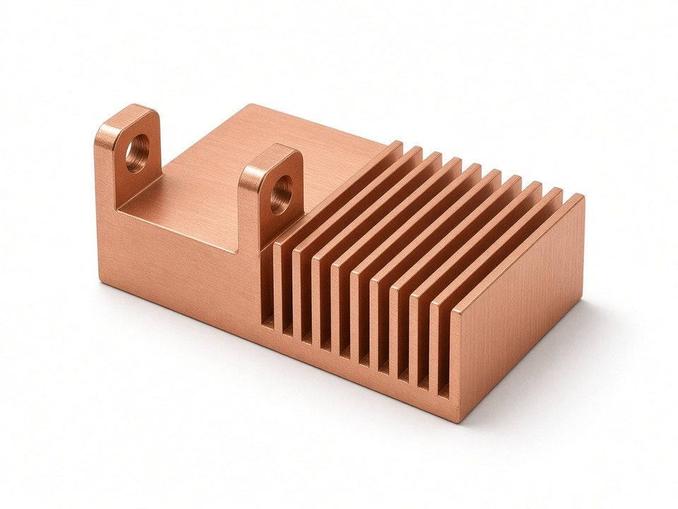
Introduction
Copper is a go-to material when a part must move electrical current or heat efficiently. That makes it valuable in busbars, electrical contacts, heat exchangers, RF components, and cooling hardware—but the same softness and ductility that make copper useful can make it frustrating to cut cleanly and hold accurately.
We wrote this guide for design engineers, buyers, and machinists selecting or producing precision copper components. We’ll compare common copper and copper-alloy grades, explain the practical causes of gummy chips and dimensional drift, and share tooling, DFM, workholding, and finishing advice you can apply to a real drawing.
The first machining decision is often not a cutting parameter: it is choosing a grade that delivers the conductivity and strength the part needs without making production needlessly difficult.
Shop context
What we check on copper drawings before quoting
- Grade and temper first: C110/C101 favor conductivity but gum up tools; C145 (tellurium) machines cleaner when conductivity can trade a little.
- Call out electrical-contact, sealing, and mating faces on the 2D—soft copper marks easily, and those surfaces drive workholding and finish choices.
- We quote milling, turning, turn-mill, or Swiss from the drawing with no MOQ once grade, temper, critical tolerances, and inspection needs are clear.
Is Copper Suitable for CNC Machining?
Yes. Copper can be CNC milled and turned into accurate parts, but machining it is more challenging than machining aluminum or free-cutting brass. Pure copper is soft, ductile, and prone to forming long chips that cling to the tool. A dull edge, unsuitable chip load, or poor chip evacuation can quickly show up as a smeared finish, burrs, or inconsistent dimensions.
Is machining copper difficult? It can be, especially with high-purity grades and delicate features. It is manageable when we match the alloy to the function, use sharp tooling with appropriate geometry, maintain a real cutting load, control heat, and plan the workholding and inspection around the part’s geometry.
Choose copper when performance leads
Use copper where electrical or thermal conductivity, corrosion behavior, or a specified copper property is central to the design. It is often worth the additional machining care for conductive contacts, busbars, and heat-transfer parts.
Compare alternatives when it does not
If conductivity is not a functional requirement, brass may be easier to machine and less costly to process. Aluminum is lighter and generally easier to cut, making it a practical alternative for some housings and heat-transfer designs.
Why Copper? Key Properties for Industrial Applications
Material selection is a balance: copper offers a combination of conductivity, corrosion behavior, and formability that can be difficult to replicate in one substitute. Those advantages come with greater density, material cost, and machining effort than common alternatives.
Electrical and thermal conductivity
Electrical conductivity is commonly expressed as a percentage of the International Annealed Copper Standard (IACS). High-conductivity copper grades are used for busbars, connectors, contacts, and current-carrying parts. Copper also transfers heat effectively, which is why it appears in heat sinks, cold plates, and thermal interfaces. Actual performance depends on grade, temper, product form, and specification.
Corrosion resistance and surface behavior
Copper forms a surface oxide and can develop a patina over time. In many environments it provides useful corrosion resistance, but the oxide or tarnish may be unacceptable on a cosmetic surface or electrical contact. Copper and some copper alloys also have antimicrobial properties; that characteristic alone does not establish suitability for a particular medical or hygiene application.
Trade-offs against brass and aluminum
Copper is relatively dense and can cost more to buy and machine than aluminum or brass. Brass often cuts more cleanly, while aluminum is lighter and commonly offers faster, easier machining. The right comparison is the complete part requirement: conductivity, operating environment, mechanical loading, finish, volume, and total manufacturing cost.
Common Copper Grades for CNC Machining
The table is a material-selection starting point, not a substitute for the drawing’s material standard or a supplier’s mill test report. Conductivity figures and relative machinability ratings are approximate; they vary with product form, temper, specification, and rating method. For machinability, 100 is commonly used as a reference for free-cutting brass, not as a universal scale.
| UNS number | Common name | Typical conductivity | Relative machinability | Typical reason to consider it |
|---|---|---|---|---|
| C10100 | Oxygen-free electronic (OFHC) copper | About 101% IACS | Low, often around 20 | High purity, vacuum, and demanding conductivity applications |
| C11000 | Electrolytic tough pitch (ETP) copper | About 100% IACS | Low, often around 20 | Common high-conductivity general-purpose copper |
| C14500 | Tellurium copper | Often around 90% IACS | High; ratings vary by source | Improved machinability while retaining useful conductivity |
| C26000 | Cartridge brass | Roughly 28% IACS | Low to moderate | Formability and general brass applications where conductivity is secondary |
| C36000 | Free-cutting brass | Roughly 25–28% IACS | Very high; reference grade near 100 | Machinability for non-electrical parts, subject to lead restrictions |
| C51000 | Phosphor bronze | Often around 15% IACS | Low to moderate | Spring, fatigue, and wear-related applications |
| C63000 | Aluminum bronze | Often in the single digits to low teens % IACS | Low to moderate | Strength and wear or corrosion demands, depending on service |
Reading a UNS designation on a drawing
UNS means Unified Numbering System. Its letter prefix identifies a broad material family, while the digits identify a particular alloy or composition. A drawing that calls out C11000, for example, is identifying a copper grade; the material specification, product form, temper, and any required certification should still be stated or referenced clearly. A UNS number by itself does not define every mechanical property or delivery condition.
How to Pick the Right Copper Grade
Start with the function, not the material currently listed on a predecessor part. Ask how much conductivity is required, whether the part carries a structural load, what the service environment is, and whether a finish or compliance requirement changes the choice.
| Design priority | Grade direction to evaluate | Selection check |
|---|---|---|
| Maximum purity or vacuum use | C10100 | Confirm the required purity, oxygen content, product form, and service specification. |
| General high-conductivity copper | C11000 | Check conductivity and mechanical requirements against the selected temper. |
| Copper function with better machinability | C14500 | Verify the conductivity trade-off is acceptable for the circuit or thermal path. |
| Non-electrical geometry prioritizing fast machining | C36000 or another brass | Review lead content, market rules, strength, and conductivity before substitution. |
| Spring or wear performance | C51000 or C63000, as applicable | Match alloy and temper to loading, fatigue, wear, and corrosion conditions. |
C11000 vs. C14500 vs. brass
Choose C11000 when high conductivity is a primary requirement and its machining behavior is acceptable for the feature set. Consider C14500 when the part still needs copper-like conductivity but the operation would benefit from a more machinable grade. Consider brass when the component is not intended to conduct current or heat at copper-grade levels and machinability is the larger priority.
Do not treat a material substitution as a machining-only decision. It can change electrical resistance, heat flow, strength, corrosion behavior, plating response, and compliance status. For example, C36000 contains lead and may be restricted for certain products or markets. Confirm the applicable RoHS requirements and any relevant exemptions or customer-specific rules rather than assuming one global status.
Temper is part of the material callout
Temper affects hardness, strength, ductility, and how a copper product behaves under a cutter. O commonly denotes an annealed condition, while H designations indicate strain-hardened conditions. HR may identify a hot-rolled condition in some product standards or forms. Temper terminology and availability depend on the applicable specification, so call out the exact standard and condition required rather than relying on an ambiguous shorthand.
Technical Challenges in Copper CNC Machining
Copper’s machining problems are connected. A chip that fails to break can recut against the surface, add heat, load the tool, and damage the finish. Solving the cause is more effective than trying to polish out the result.
Gumminess and built-up edge (BUE)
Ductile copper can adhere to a cutting edge, forming built-up edge. The result may be a rough or torn finish, unstable dimensions, and increasing tool load. A dull or damaged edge, rubbing at too-light a feed, unsuitable rake geometry, and poor chip evacuation can contribute. We address the cause with a sharp polished tool, positive geometry suited to copper, a chip load that actually cuts, and reliable chip removal.
Heat generation and thermal expansion
Copper conducts heat away from the cutting zone efficiently, but that does not prevent the workpiece and fixture from warming during a cycle. Temperature change can shift dimensions, especially on thin or closely toleranced features. Use a stable coolant or air strategy, avoid long periods of chip recutting, and allow parts and inspection equipment to reach a consistent temperature when the tolerance warrants it.
Work hardening
Repeated rubbing or shallow, interrupted cuts can deform the surface rather than remove material cleanly. That local deformation can harden the cut zone and make the next pass less predictable. Keep the tool sharp, avoid dwelling, and use a consistent chip load. Plan finishing passes so they remove material instead of lightly burnishing the surface.
Chip control and burrs
Pure copper often produces long, stringy chips. They can wrap around a tool or part, scratch finished faces, and create a safety hazard during clearing. Use a geometry and cutting condition that promotes chip breaking, direct coolant or air to the cutting zone, and program toolpaths to avoid recutting chips. Plan edge-breaking operations where burrs could affect assembly or contact performance.
Tool wear and tool choice
A sharp tool matters more than simply selecting the hardest tool material or running at the highest speed. Polished carbide is a common starting choice; PCD may be evaluated for suitable long-run or high-finish applications. Tool geometry, coating compatibility, rigidity, and the specific copper grade all matter. Validate tool life and finish on the actual setup.
Tooling, Speeds, and Feeds for Copper
Start with a sharp, polished carbide tool with positive rake and clearance appropriate to the operation. For selected production applications, PCD can be considered, but the correct choice depends on grade, toolpath, machine rigidity, surface requirement, and production volume. A tool that rubs because the feed is too low may perform worse than a tool cutting at a moderate, consistent load.
Use as a trial window
The ranges below are broad starting points for carbide and must be validated against the toolmaker’s data, machine, setup, material temper, and coolant. They are not guaranteed production parameters. Confirm tool load, chip shape, finish, temperature, and dimension during a controlled trial.
| Material / operation | Starting cutting speed | Starting feed range | Watch for |
|---|---|---|---|
| C10100 / C11000 milling | 120–300 m/min (400–1,000 sfm) | 0.02–0.10 mm/tooth | Stringy chips, rubbing, and finish changes as the tool warms |
| C14500 milling | 150–300 m/min (500–1,000 sfm) | 0.03–0.12 mm/tooth | Chip evacuation and grade-specific tool load |
| C11000 turning | 120–300 m/min (400–1,000 sfm) | 0.05–0.20 mm/rev | Chip entanglement and BUE at light cuts |
| C14500 turning | 150–300 m/min (500–1,000 sfm) | 0.05–0.20 mm/rev | Surface finish, insert geometry, and chip break |
| Brass, including C36000 | Use the insert maker’s brass guidance; higher speeds may be feasible | Set by tool, feature, and machine rigidity | Lead compliance, burrs, and workholding |
Choose coolant for chip removal and stability
Flood coolant can help flush chips and moderate temperature in milling and turning. Mist or air blast may suit open operations where chip evacuation is the main need and process requirements allow it. Minimal lubrication can reduce friction in selected setups, but it is not a universal substitute for flood coolant or a reliable chip-clearance plan. Check coolant compatibility with the copper, machine, subsequent cleaning, and any electrical-contact or plating requirements.
If finish deteriorates, first inspect the edge, chip flow, and actual cutting engagement. Raising speed without correcting rubbing or recutting can make a bad condition worse. Sharp tooling and a consistent chip load are usually a better first adjustment than maximum spindle speed.
CNC Milling vs. CNC Turning for Copper Parts
The best process depends on the part’s dominant geometry. Milling suits plates, blocks, pockets, and multi-face features; turning is efficient for rotational features such as shafts, sleeves, and bushings. Combining operations can reduce handling and preserve feature relationships when the drawing requires it.
Milling: slots, pockets, and chip evacuation
For slots and pockets, plan a toolpath that lets chips escape instead of packing at the bottom of a feature. Avoid repeatedly cutting through accumulated chips, particularly on deep pockets or narrow channels. Use a suitable flute count and geometry, maintain engagement, and consider staged roughing followed by a controlled finishing pass when surface quality or tolerance requires it.
Turning: geometry, chip breaking, and finish
On a lathe, select insert geometry for ductile copper and the target operation. A sharp edge and an effective chip breaker can improve chip control without relying on an unnecessarily light cut. Support slender work securely, manage overhang, and protect finished diameters from chips curling back across the surface.
When multi-axis machining helps
Multi-axis machining can reach multiple faces or complex angled features with fewer setups. Fewer re-clamp operations can help preserve feature relationships on a copper heat sink, manifold, or irregular conductive component. The value depends on the design: an added axis is not automatically better if the part can be produced accurately and economically with a simpler setup.
Achieving Precision and Tolerances on Copper
Is precision machining hard? It is achievable, but copper’s softness, thermal movement, and tendency to burr mean the process needs deliberate control. The more demanding the tolerance, the more important it is to stabilize the material and fixture, define a repeatable sequence, and inspect the dimensions that matter to assembly or function.
On a thin copper plate, for example, heavy clamping can distort the part while a pocketing operation warms one face more than the other. A stable fixture, balanced material removal, appropriate coolant, and consistent inspection temperature can be more important than adding a tighter machine setting.
Practical accuracy controls
-
1
Calibrate and warm up
Use a maintained, calibrated machine and allow thermal warm-up before close-tolerance work. Check the work offset and tool condition before cutting the production feature.
-
2
Stabilize the part and datum scheme
Choose repeatable datums, support thin sections, and avoid clamping forces that bend soft copper. Keep the inspection references consistent with the drawing.
-
3
Probe and manage tool offsets
Use probing where appropriate to establish work location and verify setup. Track tool wear and update offsets in a controlled way rather than compensating blindly for thermal drift.
-
4
Inspect at the right process stage
Check critical dimensions in process, then confirm drawing requirements after finishing or plating if those steps can change size. Match the measurement method to the feature and tolerance.
What are the 5 axes of machining?
A five-axis machine controls three linear movements—X, Y, and Z—plus rotation around two axes, commonly identified as A, B, or C depending on the machine configuration. These rotations let the tool or workpiece approach several faces and angles without repeated manual repositioning. This can benefit copper heat sinks and manifolds with angled passages or multi-face features, provided the design and tolerance justify the setup.
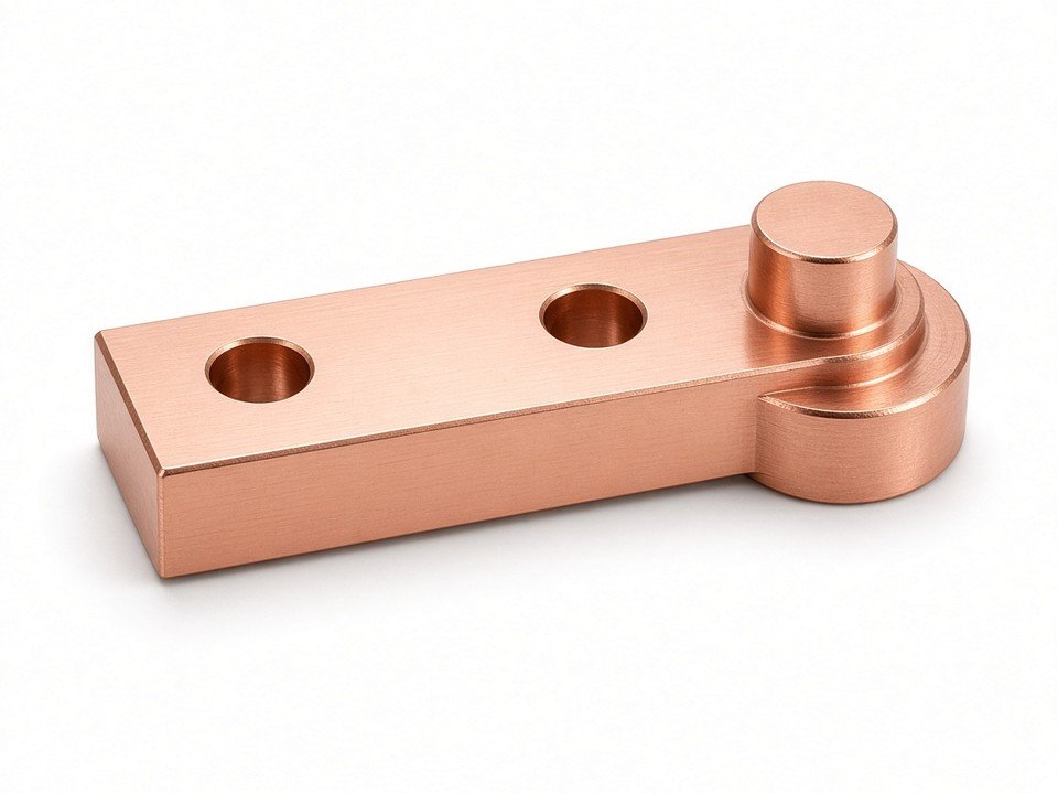
Design for Manufacturability (DFM) Tips for Copper Parts
A copper part that is easy to locate, support, cut, and inspect is more likely to meet its functional dimensions consistently. We recommend reviewing the following details before the drawing is released for production.
-
1
Avoid fragile walls and deep, narrow features
Thin walls can flex under cutting or clamping load; deep narrow pockets can trap chips and heat. Add support, open the feature where possible, or discuss a staged machining approach.
-
2
Apply tolerances where function needs them
Tighten only the dimensions that control fit, contact, sealing, or alignment. General tolerances on noncritical faces can reduce inspection and machining effort without compromising function.
-
3
Use practical corner radii
Generous internal radii let the tool clear material more robustly. A sharp internal corner may require a small tool, extra passes, or a secondary process and can increase tool stress.
-
4
Design threads for copper’s softness
Avoid overloading fine threads or thin bosses. Where the application demands repeated assembly, high clamp load, or wear resistance, evaluate thread inserts or a stronger, suitable alloy.
-
5
Include datums and fixturing features
Clear datum references, accessible locating faces, and practical clamping zones help create a repeatable setup and make inspection easier.
-
6
Specify grade, temper, finish, and inspection
Material, condition, tolerances, surface finish, plating, and inspection requirements should be explicit enough for quoting and production planning.
Example drawing callout
MATERIAL: UNS C11000 copper, temper per specified product standard; deburr and break sharp edges 0.2 mm max; critical dimensions per drawing; unmarked dimensions per stated general tolerance; contact faces uncoated; remaining surfaces clear lacquer.
This is an example structure, not a universal specification. Replace the general tolerance, temper, edge condition, and finish with values appropriate to the part and applicable material standard.
Fixtures, Workholding, and Part Handling
Copper is soft enough to mark or distort if it is clamped as though it were a stiffer steel part. The fixture must resist cutting forces without squeezing the component out of shape. Soft jaws, vacuum fixtures, and sacrificial backing plates can help, depending on the part’s shape and operation.
Avoid over-clamping thin plates and delicate walls. Support the work close to the cutting zone where practical, and review how the part will be held after a face or datum has been machined away. On repeat work, a dedicated fixture can help keep the location and clamping approach consistent.
Handling note
Finished copper surfaces scratch easily and can show fingerprints or handling marks. Separate parts with clean protective material, use clean gloves where appropriate, and keep plated or electrical-contact surfaces protected until assembly.
Surface Finishing and Post-Processing
Finishing should be selected for the part’s job, not appearance alone. Coatings can affect corrosion resistance, surface wear, electrical contact resistance, and final dimensions. Specify which faces must remain conductive or uncoated and whether the finished dimensions are measured before or after coating.
Tarnish and oxidation control
A clear lacquer can protect a decorative or exposed copper surface but is generally not appropriate on an electrical contact area. Anti-tarnish treatments may help preserve appearance or contact behavior, subject to the application and supplier process. “Passivation” is used broadly in conversation; confirm the exact conversion or protective process intended rather than relying on the term alone.
Plating options and contact performance
Nickel, tin, silver, or gold plating may be considered for corrosion protection, wear, solderability, or electrical contact performance. The right coating depends on mating material, operating environment, current, contact force, and required service life. Plating adds thickness and can change contact resistance, so include coating thickness, coverage, masking, and finished-size requirements on the specification.
Deburring and edge breaking
Copper burrs can fold over rather than break cleanly. Manual deburring, controlled tumbling, brushing, or a programmed edge-break operation may be appropriate depending on feature size and tolerance. Protect functional edges, contact faces, and small openings from rounding or abrasive residue during secondary finishing.
Appearance finishes
Brushed, polished, and bead-blasted finishes can each create a different appearance, but they may change surface texture and dimensions. If a face is an electrical contact, assess the finish and any coating together: surface films, roughness, and plating condition can influence contact resistance. State the required finish and identify functional faces on the drawing.
Common Pitfalls and Troubleshooting
When a copper operation becomes unstable, check the tool, chip path, temperature, and fixture before changing several parameters at once. The table below gives operators a practical first-pass diagnostic. See also brass turning and milling notes for practical context.
| Problem | Likely causes | First corrective checks |
|---|---|---|
| Poor or smeared finish | Dull edge, BUE, rubbing, recut chips, unstable workholding | Inspect the edge; clear chips; confirm positive geometry and a cutting feed. |
| Tool chipping | Runout, excessive engagement, vibration, damaged edge, interrupted contact | Check tool seating and runout; reduce unstable engagement; improve support. |
| Dimensional drift | Part warming, fixture movement, tool wear, inconsistent offsets | Check temperature and clamping; verify offsets and tool condition; inspect in process. |
| Burrs or folded edges | Ductile material, worn tool, poor exit path, unsuitable edge-break method | Use a sharp edge; revise the toolpath or deburring sequence; protect critical edges. |
| Galling or built-up material | Adhesion at the cutting edge, excess heat, rubbing, unsuitable lubrication | Clean and inspect the tool; restore chip load; improve coolant or chip evacuation. |
Quick operator checks before restarting
- Check the cutting edge and tool seating for built-up copper, wear, or damage.
- Confirm chips are leaving the feature and are not wrapping around the tool or part.
- Verify coolant or air is reaching the cut and the fixture has not loosened or marked the part.
- Recheck the datum, tool offset, and measurement temperature before compensating for a dimension change.
CNC Copper Machining vs. Alternative Methods
CNC machining is not the only way to make a copper component. The right route depends on production volume, geometry, material availability, surface requirements, and the time and cost of tooling or post-processing.
| Method | Often a fit when | Main trade-off to assess |
|---|---|---|
| CNC machining | Low-to-mid volumes need precise features, controlled datums, or good machined surfaces. | Material removal, machining time, and careful chip and heat management. |
| Stamping | A repeatable sheet-metal shape is needed at higher volumes. | Tooling investment and limits on thickness, geometry, and formed features. |
| Casting | A suitable alloy and design can produce a more complex near-net shape. | Tooling, casting characteristics, and possible secondary machining of critical features. |
| Copper additive manufacturing | A qualified printing process can support a geometry that is difficult to make conventionally. | Process and material qualification, surface condition, build limits, and finishing needs. |
For prototypes and low-to-mid volumes, CNC can provide direct access to precise machined surfaces and drawing-based feature control without a dedicated forming die. At larger volumes, stamping or another near-net process may improve unit economics if the geometry allows it. Compare the full route—including tooling lead time, secondary operations, inspection, and design-change risk—rather than the first quoted operation alone. See also CNC turning for conductive parts for practical context.
Applications That Rely on Precision-Machined Copper
Copper components often sit where electrical, thermal, and mechanical interfaces meet. The design must account for how the part connects to adjacent components, how it sheds or carries heat, and whether its exposed surfaces remain stable through service.
Power and electrical hardware
Busbars, connectors, contacts, and battery bus components use copper where current-carrying performance is important. Connection faces, hole position, flatness, plating, and contact pressure may all be critical to the finished assembly. See also precision tolerance strategies for practical context.
Thermal management
Heat sinks and cold plates for EV power electronics, data-center cooling, and LED systems can rely on copper’s heat-transfer behavior. Channel geometry, sealing features, wall thickness, and flat mounting surfaces should be designed with both machining access and inspection in mind.
RF, vacuum, and fluid systems
RF and microwave components, vacuum hardware, and some plumbing or marine fittings may call for copper or a copper alloy based on conductivity, sealing, corrosion, or material requirements. Confirm the specific service environment and applicable material specification.
Emerging energy applications
Battery electrical components and hydrogen electrolyzer parts are among the applications in which engineers may evaluate copper. Grade, surface condition, joining method, and chemical compatibility must be validated against the operating requirements of the specific system.
Sourcing Copper CNC Parts: What to Ask Your Supplier
Supplier selection affects more than the unit price. Ask how the supplier will control copper’s chip behavior and thermal movement, how the drawing will be interpreted, and what records will support your receiving and qualification process.
-
Material documentation
Can the supplier provide mill test reports or material certificates identifying the ordered grade and condition?
-
Compliance and traceability
Can the supplier address the applicable RoHS or customer-specific requirements, and maintain the requested material and production traceability?
-
Inspection records and samples
Which dimensions will be measured, with what equipment and report format? Can a sample run validate the drawing, finish, and assembly-critical features?
-
Machining process and thermal control
Ask about the supplier’s experience with the selected copper grade, chip management, workholding, and repeatable dimensional checks.
-
Supply continuity and sustainability
If recycled copper content or source traceability matters, ask whether the material source can document the requested information for the ordered product.
For a copper RFQ, include UNS grade and temper, which faces are electrical-contact or sealing-critical, and which dimensions need CMM versus gauge checks. We use that package to confirm milling versus turning routes, chip and thermal control, and an inspection plan before production—not a generic capability list.
Frequently Asked Questions
Is machining copper difficult?
It is more difficult than machining aluminum or free-cutting brass because copper is ductile, can form long chips, and may build up on the cutting edge. The right grade, sharp polished tooling, positive geometry, consistent chip load, and effective chip evacuation make it manageable.
Is precision machining hard?
Precision machining is achievable when the process controls the factors that move the part or measurement: temperature, workholding, tool wear, machine condition, and datum consistency. Copper may need extra attention because it is soft and thermally responsive, especially on thin sections and close-tolerance features.
How to improve CNC machine accuracy?
Maintain and calibrate the machine, warm it up before close-tolerance work, use stable workholding, probe the setup where appropriate, and manage tool offsets consistently. Inspect critical dimensions in process and avoid compensating for drift until temperature, tooling, and fixture conditions have been checked.
What are the 5 axes of machining?
They are three linear axes—X, Y, and Z—plus rotation around two axes. The machine can approach angled or multiple faces with fewer setups, which can help on complex heat sinks, manifolds, and other multi-sided copper parts.
Which copper grade is easiest to machine?
C14500 tellurium copper is a more machinable copper grade while retaining useful conductivity. C36000 free-cutting brass is generally easier to machine than pure copper, but it is a brass alloy with much lower conductivity and lead-content restrictions to consider. They are not direct substitutes without an application review.
Can copper be anodized?
Copper cannot be anodized in the same way as aluminum to create the familiar hard aluminum oxide layer. Alternatives include clear lacquer, anti-tarnish treatments, conversion coatings, and nickel, tin, silver, or gold plating, selected for the required appearance, protection, and electrical behavior.
What tolerances can CNC copper parts hold?
As a planning reference, suitable copper features may commonly be specified in the range of about ±0.025–0.05 mm, while tighter tolerances may be achievable with a suitable process and feature geometry. This is not a guarantee: part size, wall thickness, datum scheme, temper, clamping, thermal state, finish, and inspection method all affect capability. Confirm critical tolerances with the manufacturing supplier during review.
Key Takeaways
- Choose a grade based on functional conductivity, mechanical performance, environment, compliance, and cost—not machinability alone.
- C10100 and C11000 suit high-conductivity needs; C14500 can improve machinability; brass may suit non-electrical parts when its trade-offs are acceptable.
- Control gummy chips, built-up edge, heat, and burrs with sharp tools, consistent chip load, and a planned chip-evacuation strategy.
- Design practical walls, radii, threads, datums, and tolerances so the part can be supported and inspected repeatably.
- Select finishes with contact performance and final dimensions in mind, especially on electrical interfaces.
- Share the complete material, temper, finish, tolerance, and inspection requirements with your supplier before production.
Request a Quote for Your Copper Part
For a useful manufacturing review, include your 3D model, a 2D drawing that identifies the copper grade and temper, expected quantities, required finish, and inspection or documentation needs. Mark critical dimensions and identify electrical-contact, sealing, or mating surfaces. If the grade or tolerance is still under review, tell us the part’s function so we can discuss practical options.
Upload the model and 2D with grade/temper marked. If conductivity versus machinability is still open, note the function of the part—we will propose a practical copper process and inspection plan with the quote.
Request a Copper Part QuoteTalk with YJCNC
We are certified to ISO 9001 (HIC241500), ISO 14001 (HIC241501), AS9100D/EN9100 (CN044900), ISO 13485 (04526MDQ00014R100), and IATF 16949 (0565487). Confirm which certificates apply to your drawing package and end-use before release.
Share Your Copper Part Requirements
Send your drawing, material requirements, quantity, finish, and inspection needs. We’ll review the information and discuss a suitable machining approach.