YJCNC Engineering Guide
CNC Machining Tools Explained: Cutters, Inserts & Selection
Choosing a CNC cutting tool is a practical balance of workpiece material, operation, tool geometry, machine capability, and cost per part. We explain the common cutter families, insert systems, tool materials, coatings, and setup decisions that help shops produce accurate parts reliably.
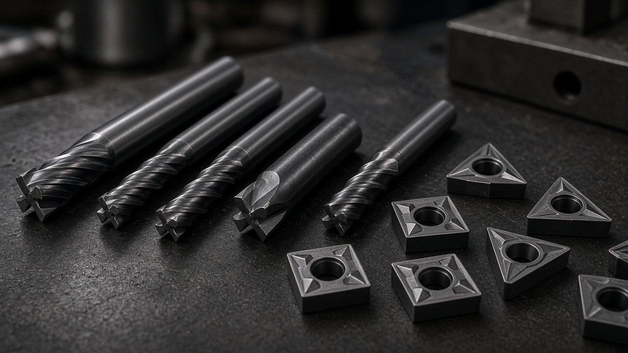
What Shops Weigh Before Picking a Cutter
Match geometry and cutting material to the workpiece and operation, then confirm that the machine, holder, and coolant can support the cut. A tool that roughs aluminum well may be a poor choice for finishing stainless or drilling a deep, small-diameter hole. Compare tool life, surface finish, cycle time, changeover effort, and scrap risk—not just the purchase price. For repeat production, record the trial and use that data on the next order.
Start with the cut
Identify the material, feature, tolerance, and whether the operation is roughing or finishing.
Prove it in context
Check the tool against holder runout, machine rigidity, coolant delivery, and cost per good part.
In practice, indexable carbide covers most steel and aluminum roughing, while solid carbide end mills dominate finishing and small features. Coating choice (TiAlN, AlCrN, diamond-like) follows workpiece chemistry more than brand preference. At YJCNC, a mid-size shop, we stock common diameters and call specialty tools only when the drawing forces them.
What Are CNC Machining Tools?
CNC machining tools are the cutting or abrasive devices that remove material from a workpiece under programmed machine motion. The cutting edge shears off small chips; the machine controls the tool or workpiece path to create the dimensions and surfaces specified by the part design. Tool geometry, sharpness, and setup all influence whether that material comes away cleanly or creates excess heat, vibration, and wear.
Most drawing packages we see lean on milling and turning first. Hole-making sits inside those programs as a sequenced set of tools. Surface grinding shows up when a tolerance or finish cannot be held reliably by cutting alone—far less often than end mills and inserts.
Milling is where shops spend the most day-to-day cutter decisions: end mills, face mills, and specialty forms for slots, pockets, profiles, and flat faces. Solid cutters and indexable bodies both appear here, and the same job may switch between them for roughing versus finishing.
Turning keeps the workpiece rotating while a stationary tool shapes diameters, faces, grooves, and threads. Indexable inserts dominate CNC lathe tooling; holder pocket geometry and chipbreaker choice usually matter more than buying another shank style.
Hole-making is rarely a single drill. Spotting, drilling, reaming, countersinking, and threading tools each answer a drawing callout—size, position, finish, or thread class—rather than a separate process family on the floor.
Grinding remains a finishing or corrective step for a minority of features: abrasive wheels remove small stock when cutting cannot hold the surface or size. We do not treat it as a peer of everyday milling and turning when stocking a general CNC tool crib.
The tool choice can change dimensional accuracy, edge quality, surface finish, cycle time, and the frequency of tool changes. A rigid, sharp tool with appropriate chip evacuation can help a pocket finish cleanly; a long, flexible setup may deflect and leave taper or chatter even if the cutter itself is suitable. Tool cost therefore matters, but it is only one part of the manufacturing result. Process capability notes for milling work live on our CNC milling page.
Milling Cutters Explained
Milling cutters are the broadest CNC tool family. A mill typically rotates while cutting, with the machine moving the tool, the workpiece, or both along the programmed axes. Solid cutters have cutting edges formed directly into the tool body; indexable cutters use replaceable inserts clamped to a reusable body.
End Mills
An end mill can cut with its sides, its end, or both, making it useful for profiles, slots, pockets, and shoulders. The form you select affects the shape it can generate and the strength or reach of its cutting edge.
- Square end mills produce flat bottoms and square shoulders and are the everyday choice for general profiling, slotting, and pocketing.
- Ball nose end mills have a rounded tip for 3D contours, curved surfaces, and sculpted forms. Their contact area changes with toolpath engagement, so step-over and finishing strategy matter.
- Bull nose or corner-radius end mills combine a flat end with a small corner radius. The stronger corner can resist chipping while still leaving a mostly flat floor.
- Roughing and high-feed end mills use edge geometry and engagement strategies intended to remove material efficiently. They need a suitable toolpath, a stable setup, and enough machine capability to manage the cutting load.
Flute count is a trade-off, not a universal ranking. Fewer flutes leave more space for chips, while additional flutes can provide more cutting edges and support a finer feed strategy when chip evacuation and material allow it.
| Flute count | Chip evacuation | Typical finish and use |
|---|---|---|
| 2 flutes | Large flute space; useful when chips need room to clear. | Common in slotting and many aluminum applications; finish depends on geometry, setup, and parameters. |
| 3 flutes | A balance of chip space and cutting edges. | Often selected for aluminum and general-purpose milling where the specific tool design supports it. |
| 4 or more flutes | Less space per flute; chip control becomes important in slots and deep pockets. | Common for steel and finishing strategies where the tool, engagement, and chip evacuation are matched. |
Face Mills and Shell Mills
Face mills and shell mills are used to machine broad, relatively flat surfaces. Their larger diameter can cover more area per pass than a small end mill, making them useful for surfacing stock or taking a planned roughing cut. Many are indexable: carbide inserts seat in pockets on the cutter body, and the usable edges can be rotated or replaced without changing the whole cutter.
Specialty Milling Tools
Specialty cutters make features that are difficult to produce efficiently with a standard end mill, or help control a particular edge form or operation.
- Dovetail, T-slot, and V-slot cutters machine undercuts and slot profiles. They are often used after a straight slot or pilot feature is made, and their reach makes secure workholding especially important.
- Keyseat cutters and slitting saws create narrow keyways, grooves, and cuts. Thin cutters can deflect, so arbor support, alignment, and conservative engagement deserve attention.
- Thread mills cut internal or external threads by interpolating a helical path. Compared with taps, they can be useful for certain tough materials, larger or varied thread sizes, and cases where a broken tool would be costly. They require suitable programming and machine motion.
Toolpath strategy shapes how much of that geometry you can use. Adaptive or trochoidal clearing can keep a planned engagement in pockets where full-width slotting would overload a solid end mill; the cutter, CAM data, workholding, and machine still have to agree. A high-feed or roughing end mill only earns its keep when the path and spindle can support the intended chip load.
Drilling and Hole-Making Tools
Hole-making often involves several tools rather than one. A drilling sequence may start with a spot, create the hole with a drill, then use a reamer, countersink, or thread tool to bring the feature to its final form. Neutral background on machining cutters is collected under Wikipedia’s cutting tool (machining) entry.
-
1
Locate and guide
Center drills and spot drills create a starting feature that helps locate the drill. Use the tool and spot geometry appropriate to the drill point and part setup.
-
2
Make the hole
Twist drills are widely used for general holes. For deep holes, peck drilling can break chips and help clear them, while through-coolant drills deliver coolant closer to the cutting edges when the machine and tool are designed for it.
-
3
Finish the feature
Reamers can size a pre-existing hole to a tighter tolerance and improve its finish when the allowance and setup are appropriate. Countersinks and chamfer mills break edges or create a defined lead-in around a hole.
Do not assume a drill alone will deliver the finished size or surface required by a drawing. Hole tolerance, material condition, depth, tool runout, chip control, and the selected finishing method all affect the result.
Turning Tools and Lathe Cutters
Turning tools work differently from milling cutters. In conventional turning, the workpiece rotates and the tool is held in a fixed position or follows a programmed path. In milling, the cutter rotates to create the cut. Turn-mill machines combine operations, but each tool still needs the correct spindle, holder, and machine mode.
Common lathe tooling includes external turning tools for outside diameters and faces, boring bars for internal features, grooving tools for narrow recesses, parting blades for cutoff, and threading tools for internal or external threads. On repeat shaft and bushing work, shops usually decide insert grade, chipbreaker, and nose radius first, then confirm the holder pocket and approach angle—buying another shank style is secondary. Tool geometry and insert selection need to suit the material, direction of cut, feature access, and chip-control requirements.
Holding the turning tool
Tooling may be mounted in CNC turret stations or in quick-change systems, depending on the machine and production setup. On a turret, station choice and tool orientation must match the machine's configuration and program. Quick-change systems can support efficient setup changes where the machine and holders are designed to use them. On any lathe, secure clamping, correct center height, and controlled overhang help reduce vibration and dimensional variation.
Indexable Carbide Inserts: Why Shops Rely on Them
An indexable insert is a replaceable cutting edge clamped into a reusable holder or cutter body. A screw, clamp, or other retention method secures the insert; a shim may sit beneath it to protect the pocket and support the cutting edge. When an edge wears, the operator can rotate the insert to a fresh edge or replace it, then reset or verify offsets as the setup requires.
The economic appeal is straightforward: the holder is reused, and multiple usable edges can be available on one insert. Compared with regrinding a solid tool, indexing can reduce the time spent restoring an edge. On the floor, most of the debate is grade and chipbreaker for the alloy on the drawing, not whether to use inserts at all. The complete decision still depends on insert price, edge count, tool life, change time, and whether the insert produces the required part quality.
Reading an ISO Insert Designation
Many turning inserts follow an ISO-style code in which character positions describe attributes such as insert shape, clearance angle, tolerance, clamping or chipbreaker style, size, thickness, and nose radius. The formal designation rules are published in ISO 1832; supplier catalogs still need a final check because product-family conventions can add options beyond the base code. Rather than memorizing a string, verify that the code matches the holder pocket and the intended cut.
Insert Shapes and Geometry
Insert shape influences the number of usable edges, access to shoulders, and strength of the cutting corner. A stronger edge can tolerate heavier or less stable cutting conditions, while a sharper or more accessible shape may reach details more easily. No shape is best for every feature.
- Triangular inserts can offer several usable edges and access to some profiles, though their smaller included angle is generally less robust than a square or round form.
- Square inserts offer a sturdy edge and are often useful for general turning and shoulder work, subject to holder geometry and clearance.
- Diamond inserts provide access to angles and profiles. The included angle affects edge strength, so a sharper point may reach tighter features but can be more vulnerable.
- Round inserts have a strong continuous edge and can support heavy cuts or profiling, but the contact area and cutting forces vary with depth of cut.
Chipbreakers direct and curl chips. Roughing geometries are commonly designed to handle heavier chip loads, while finishing geometries are shaped for lighter cuts and controlled chip formation. Material, feed, depth of cut, and rigidity determine whether a chipbreaker performs as intended; match its recommended operating range rather than selecting by label alone.
When to Replace an Insert
Inspect an insert when dimensions, finish, sound, or chip shape begin to change. Common wear patterns include flank wear along the relief face, crater wear on the rake face, and edge chipping. Built-up material on the edge, discoloration from heat, or a sudden change in cutting load can also signal that the edge needs attention.
Set a repeatable change point
Use tool-life trials and inspection records to establish a replacement threshold before wear causes out-of-tolerance parts. For a critical feature, schedule a change with a reasonable safety margin based on observed production data, then review the threshold when material batches, geometry, or cutting conditions change.
Cutting Tool Materials
Tool materials balance hardness, which helps resist wear, against toughness, which helps the edge survive impact and interrupted cutting. The workpiece, speed, cut stability, tool geometry, and budget all shape the choice. Harder is not automatically better if the setup is prone to vibration or the edge is likely to be shocked.
High-Speed Steel (HSS)
HSS is tougher and generally more forgiving than many harder tooling grades, but it does not retain hardness at cutting temperatures as well as carbide. It remains useful for some low-speed work, general-purpose drills, and low-volume operations where a lower initial tool cost or a forgiving edge is valuable. Its limitations become more apparent when higher cutting speeds and production rates are needed.
Carbide
Cemented carbide combines hard carbide particles with a metallic binder, commonly cobalt. Grade and performance depend on factors that include carbide grain size, binder content, and the manufacturer's formulation. In broad terms, finer grains can support wear resistance and edge sharpness, while greater toughness may be desirable for interrupted cuts or less stable setups. Carbide dominates modern CNC cutting because it can support productive cutting speeds across many materials, provided the grade, geometry, and machine conditions are matched.
Cermet, Ceramic, CBN, and PCD
These advanced cutting materials are selected for particular workpiece and cutting conditions rather than as universal replacements for carbide. Cermets can be used in finishing applications where their wear behavior and finish capability suit the job. Ceramics can support high-speed machining in selected materials and stable conditions. Cubic boron nitride (CBN) is associated with machining hardened steels, while polycrystalline diamond (PCD) is used for suitable non-ferrous and abrasive materials. Consult tooling guidance and prove the application: edge sensitivity, impact, workpiece condition, and setup rigidity can make or break the result.
Plain carbon-steel tooling is a legacy, low-speed option we almost never put on a CNC spindle for production work. It loses hardness at modest cutting temperatures; the lower purchase cost rarely offsets limited speed, wear resistance, or tool life compared with HSS or carbide.
Tool Coatings and Surface Treatments
A coating can reduce friction, resist wear, and help protect a tool from heat. It does not correct the wrong geometry, poor chip evacuation, or an unstable setup. Coating choice should follow the tool substrate, workpiece, cutting temperature, and operation; the same coating can behave differently on a drill and a milling cutter.
TiN, TiCN, and TiAlN/AlTiN
Titanium nitride (TiN) is commonly recognizable by its gold-colored appearance and is used across a range of general applications. Titanium carbonitride (TiCN) is typically harder than TiN and may be selected where abrasion resistance is important, although application limits still depend on the product and cutting conditions. Titanium aluminum nitride (TiAlN) and aluminum titanium nitride (AlTiN) are designed for higher-temperature cutting situations and are often considered for demanding milling in steels and other suitable materials. Color can offer a visual clue, but it is not a reliable way to identify a coating or grade—check the supplier's documentation.
DLC and Specialty Coatings
Diamond-like carbon (DLC) and other low-friction surface treatments can be useful in selected aluminum and non-ferrous applications, where limiting built-up material on the cutting edge may help. Some specialty tool families use nano-layered or multilayer coatings designed to combine properties across changing cutting conditions. Coating names alone are not enough to select a tool: use the manufacturer's application data and consider coolant, speed, material condition, and tool geometry together.
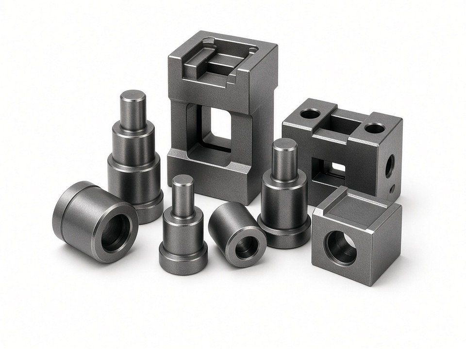
Tool Holding and Setup Basics
A suitable cutter can still produce poor results if it is held poorly. Runout means the tool does not rotate concentrically; excessive runout can overload one cutting edge and contribute to uneven wear, poor finish, and inconsistent dimensions. Excessive stick-out reduces rigidity and makes vibration or deflection more likely. Keep the tool projection as short as the feature allows, while maintaining safe clearance and access.
- Collet chucks are versatile and convenient for holding many shank tools; choose the correct collet, keep contact surfaces clean, and follow the holder's clamping guidance.
- End mill holders use a positive drive feature for suitable shank tools and can be useful when secure torque transmission is a priority.
- Hydraulic and shrink-fit holders can provide a compact, concentric holding solution when used with compatible tooling and the required setup equipment and process.
A machine tool interface such as CAT, BT, or HSK must match the spindle and holder. Shops also benefit from a consistent tool library: record tool number, description, diameter, gauge length, holder, and offsets so CAM, setup documentation, and the machine agree. Offset management is especially important when an insert is indexed, a cutter is replaced, or a preset tool is returned to the machine. Where CAM and presetters exchange structured cutter data, the industry model behind many catalogs is ISO 13399; the standard only helps if the shop keeps dimensions, holders, and offsets accurate.
How Shops Choose the Right Cutting Tool
We walk the same checks on most jobs—material and feature first, then geometry, machine, and a recorded trial—so a tooling issue is not confused with workholding, programming, machine condition, or material variation.
-
1
Identify the material and feature
Record the alloy or material condition, feature geometry, tolerance, surface requirement, and available access before selecting a tool.
-
2
Choose a tool family and geometry
Select the cutter, drill, turning tool, or insert shape that can reach the feature and produce the required edge form.
-
3
Verify the machine and setup
Check spindle, rigidity, holder interface, reach, runout, workholding, RPM range, and coolant delivery.
-
4
Set and document a trial
Begin with toolmaker guidance, confirm chips and cut stability, inspect the part, and record tool life and changes made.
Workpiece Material
Material affects heat, chip formation, abrasion, edge adhesion, and the strength needed at the cutting edge. Aluminum often calls for sharp geometry and chip clearance; steels need grades and coatings suited to the material and cut; stainless steel and titanium can require careful control of heat and work hardening. Cast iron is abrasive and often produces a different chip form from ductile metals. Plastics need sharp tools and attention to heat and chip evacuation to reduce melting or edge damage. Treat these as starting considerations, not substitutes for the exact material grade and toolmaker data.
Machining Operation
Separate roughing, semi-finishing, and finishing. Roughing prioritizes controlled material removal and tool strength. Semi-finishing establishes a more consistent allowance. Finishing prioritizes dimensional control and surface quality, often with a lighter engagement and a tool geometry selected for the final feature. A roughing cutter that is productive in a large pocket may not be the right option for a thin wall or a small finishing pass.
Toolpath strategy changes how the cutter engages. Trochoidal and adaptive-clearing paths can maintain a more controlled engagement in some operations, which may allow a different cutter or cutting condition than full-width slotting. Engagement-aware CAM paths only help when tool data, machine capability, workholding, and post-processed motion are correct; a strategy does not eliminate the need to manage chip load, reach, and rigidity.
Machine Capability
Confirm spindle power and torque, available RPM, machine rigidity, axis behavior, and coolant delivery. A tool may require a speed the spindle cannot reach or a cutting load the setup cannot support. Long-reach tools and slender boring bars need particular attention to deflection. Verify that the holder interface fits the spindle, and that the full tool assembly clears the workpiece, fixture, and machine envelope throughout the programmed path.
Cutting Parameters and Coolant
Cutting speed, feed per tooth or revolution, depth of cut, radial engagement, and coolant work as a system. Too much feed or engagement can overload an edge; too little feed can cause rubbing rather than clean cutting. Flood coolant, air blast, and minimum-quantity lubrication (MQL) each change heat and chip evacuation differently; dry or MQL runs are application-dependent and must stay compatible with the material, operation, safety practice, and finish requirement. Always verify recommended limits and application notes from the tool manufacturer.
| Workpiece group | Shop-typical carbide end-mill Vc starting band (order of magnitude) | First checks during a trial |
|---|---|---|
| Aluminum alloys | About 150–300 m/min | Sharp geometry, chip clearance, spindle limit, and built-up material. |
| Carbon and alloy steels | About 90–150 m/min | Grade, coating, engagement, coolant, and cut stability. |
| Stainless steels | About 40–100 m/min | Work hardening, heat, chip control, and consistent feed. |
| Titanium alloys | About 25–60 m/min | Heat management, tool engagement, machine rigidity, and coolant delivery. |
| Cast iron | About 60–120 m/min | Abrasive wear, chip or dust management, and grade suitability. |
Bands above are shop-typical order-of-magnitude starting ranges for coated carbide end mills under common emulsion or dry conditions—aligned with the scale published in general machining data handbooks, not a grade-specific catalog line. Exact limits move with alloy, hardness, diameter, flute count, coating, engagement, coolant, machine, and holder. Use the tooling supplier’s data for the exact tool, and calculate feed from the recommended chip load and the actual number of cutting edges.
Cost per Part, Not Price per Tool
A low-cost cutter may be expensive in production if it wears quickly, slows the cycle, demands frequent changes, or increases scrap risk. Compare the tool expense alongside cycle time, changeover time, inspection burden, and the cost of a nonconforming part. Use actual shop data where possible and compare like-for-like operations.
| What to compare on a batch | Lower purchase-price cutter | Longer-life coated carbide |
|---|---|---|
| Unit tool price | Lower at the crib | Higher at the crib |
| Parts per edge (typical shop pattern) | Fewer good parts before change | More good parts before change when grade matches the alloy |
| Changeovers on a mid-size lot | More stops; more offset checks | Fewer stops when life holds |
| Batch tooling cost tendency | Can rise once life and change time are counted | Often lower per good part despite higher unit price |
| Still missing from any crib quote | Cycle-time difference, scrap risk, and inspection burden—add these from measured production data before locking a purchase. | |
Use supplier quotations and your measured parts-per-edge and change time; the table states direction of the comparison, not catalog prices. Public distributor ranges for general-purpose carbide end mills commonly span from low tens to low hundreds of USD depending on diameter, flute count, and coating—exact figures belong on the quote, not in a generic model.
Common Tool Selection Mistakes
Several avoidable choices can shorten tool life or make a stable process difficult to repeat. We look for these issues early when troubleshooting a cut.
- Using a general-purpose tool for hardened or exotic materials. These materials may need a specialized grade, edge preparation, and cutting strategy rather than a standard tool.
- Ignoring holder runout or excessive stick-out. Both can make the cut unstable and concentrate wear on one edge.
- Running too fast or too slowly for the tool system. Speed, feed, engagement, substrate, coating, and coolant need to work together; changing one number in isolation may not solve the problem.
- Choosing by purchase price alone. Track tool life and time per good part, including changeovers and scrap, to see the true cost.
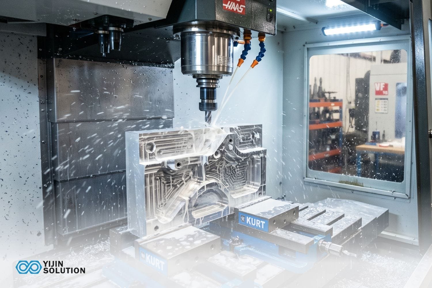
Tool Wear, Life, and Maintenance
Tool life depends on the material, cutting conditions, setup, and the point at which the shop defines an edge as no longer suitable. Common wear mechanisms include abrasion from hard particles, adhesion or built-up material at the edge, diffusion at elevated temperature, and thermal fatigue caused by repeated temperature changes. These mechanisms can appear together.
Inspect the edge
Look for flank or crater wear, chips, cracks, built-up material, and unexpected discoloration under suitable inspection conditions.
Inspect the result
Check part dimensions, surface finish, burrs, and chip form against the process requirements and tool-life record.
Replace an insert or cutter when it reaches the documented wear threshold, produces a quality change, or shows damage that makes continued use unsafe or unpredictable. Regrinding may be appropriate for some solid tools when the tool and service support it; indexable inserts are generally indexed or replaced instead. Keep tooling clean, protect edges from impact, store tools so they cannot rub against one another, and preset or verify tool length and diameter before returning them to production. Spindle-load or vibration signals can flag wear earlier, but they only help when tied to an established process and checked against the edge and the part.
Frequently Asked Questions
What cutting tools are used on a CNC machine?
Common tools include end mills, face mills, drills, reamers, taps, thread mills, and turning inserts. The selection depends on the machine process and the features on the part.
What are the 3 types of milling cutters?
A common introductory grouping is peripheral or slab cutters, face mills, and end mills. Classifications vary by source and may describe cutter form, how the cutter engages the work, or the operation being performed.
Which mill is the most commonly used cutting tool in CNC applications?
The square end mill is the most widely used general-purpose milling cutter in many CNC applications because it can make profiles, slots, shoulders, and pockets. The best choice still depends on the material, feature, and operation.
What do I need to start CNC milling?
You need a suitable CNC machine and controller, CAD/CAM software or another appropriate programming workflow, workholding, compatible tool holders, a small starter tool set, coolant or air blast appropriate to the operation, and required safety gear. Tool offsets, setup procedures, and safe program verification are also essential parts of getting started.
What is the difference between a carbide insert and an end mill?
A carbide insert is a replaceable cutting edge clamped into a holder or cutter body. An end mill is typically a one-piece tool with cutting edges formed into its body, although some end mills are also designed with replaceable heads or inserts.
How often should cutting tools be replaced?
There is no fixed interval that fits every job. Replace a tool based on observed wear, part quality, cutting behavior, and recorded tool-life data; set a repeatable threshold that prevents wear from producing nonconforming parts.
Putting a Tool Choice into Production
Choosing CNC machining tools becomes more manageable when we start with the workpiece material and operation, then check tool geometry, substrate, coating, machine capability, and setup. Milling cutters, drills, turning tools, and indexable inserts each solve different cutting problems. The best selection is the one that meets the drawing requirements consistently at a competitive cost per good part.
For a first crib, stock a few square end mills in the diameters your drawings actually use, a ball-nose or corner-radius tool when contours appear, spotting and twist drills for common holes, a face mill when stock facing is routine, and one insert holder with a compatible general-purpose insert for the lathe or mill work you expect. Add reamers or chamfer tools after the feature callouts demand them, and keep duplicates of the cutters that stop a job when they wear out.
For a new job, document the tool and holder, verify manufacturer-recommended cutting conditions, inspect the first parts, and use measured wear and cycle data to refine the process. At YJCNC, we review customer drawings and specifications to determine appropriate machining processes and inspection requirements for custom components, from prototypes through repeat production, subject to project requirements.
Capability detail for rotary work is on our CNC turning page.
Contact YJCNC about your machining projectDiscuss your requirements
YJCNC is certified to ISO 9001 (HIC241500), ISO 14001 (HIC241501), AS9100D/EN9100 (CN044900), ISO 13485 (04526MDQ00014R100), and IATF 16949 (0565487). Confirm which certificates apply to your drawing package and end-use before release.
Need help planning a precision-machined component?
Share your drawing, material, quantity, tolerances, and finish requirements with our team. We can review the project and discuss suitable CNC milling, turning, turn-mill, or Swiss-type machining options.