CNC Manufacturing Guide
CNC Milling vs CNC Turning: How to Choose the Right Process for Your Drawing
The right machining process starts with the geometry on your engineering drawing—not with a default preference for one machine. We explain how to identify milling and turning features, read the drawing clues that matter, and decide when a combined process is worth considering.
Quick Answer
Answer first: Choose milling when planar features dominate; choose turning when the envelope and datums revolve about one axis; choose hybrid when the drawing mixes both—and let DFM confirm before you lock a supplier process.
CNC milling suits prismatic parts and features formed on flat or angled faces; CNC turning suits parts whose main geometry is rotational. If your drawing combines a turned body with flats, cross-holes, slots, or milled pockets, a turn-mill or a planned sequence of operations may be appropriate.
At YJCNC, we start by locating the part’s primary geometry and functional datums, then review tolerances, access, material, and order quantity. That drawing-led review helps us select a workable process rather than forcing every feature into one machine setup.
A simple rule is useful, but it is not the whole decision. A block-shaped housing can contain turned bores, while a shaft may need milled keyways or wrench flats. The details on the drawing determine whether a single process, a combination, or a secondary operation makes sense. Further process detail lives under turn-mill with live tooling.
Shop context
Milling vs turning — drawing-led rule of thumb
- If the primary datum and envelope revolve around one axis, start with turning; if planar faces and hole patterns dominate, start with milling.
- Hybrid drawings (turned body + milled flats/keyways) often run turn-mill or two ops—YJCNC reviews this during DFM from the drawing.
- No MOQ: one-off process trials are common before locking a production route.
When to Choose CNC Milling
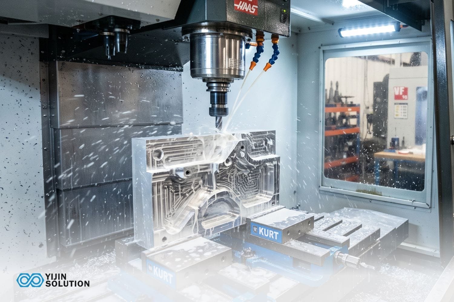
In milling, the cutting tool rotates and removes material as it moves across a workpiece held in a fixture. The process is a natural fit when the drawing is dominated by planar faces, pockets, slots, holes, or contours that are not concentric around one axis.
Geometry and features that favor milling
Look for a part that is fundamentally a block, plate, bracket, or housing. Flat mounting surfaces, rectangular pockets, non-round profiles, and hole patterns located from edges or datums often point toward milling. Multi-sided parts may also benefit from 4-axis or 5-axis machining when the required faces and orientations can be reached efficiently.
Typical milling examples
Mounting plates, brackets, and equipment housings are common examples. For instance, a plate with a rectangular outline, a shallow pocket, and a pattern of holes dimensioned from two datum edges is usually easier to define as a milling job than as a turning job. If the same part also has a precision cylindrical bore, the bore’s tolerance and relationship to the other features may influence the sequence or call for an additional operation.
Milling is a strong candidate when
The part has several non-round faces, pockets, slots, or hole patterns located from a planar datum scheme. The main geometry does not revolve around one centerline.
Review the setup when
Features lie on multiple sides or at different angles. Access, workholding, and datum transfer can affect how many operations are needed and how relationships are maintained.
When to Choose CNC Turning
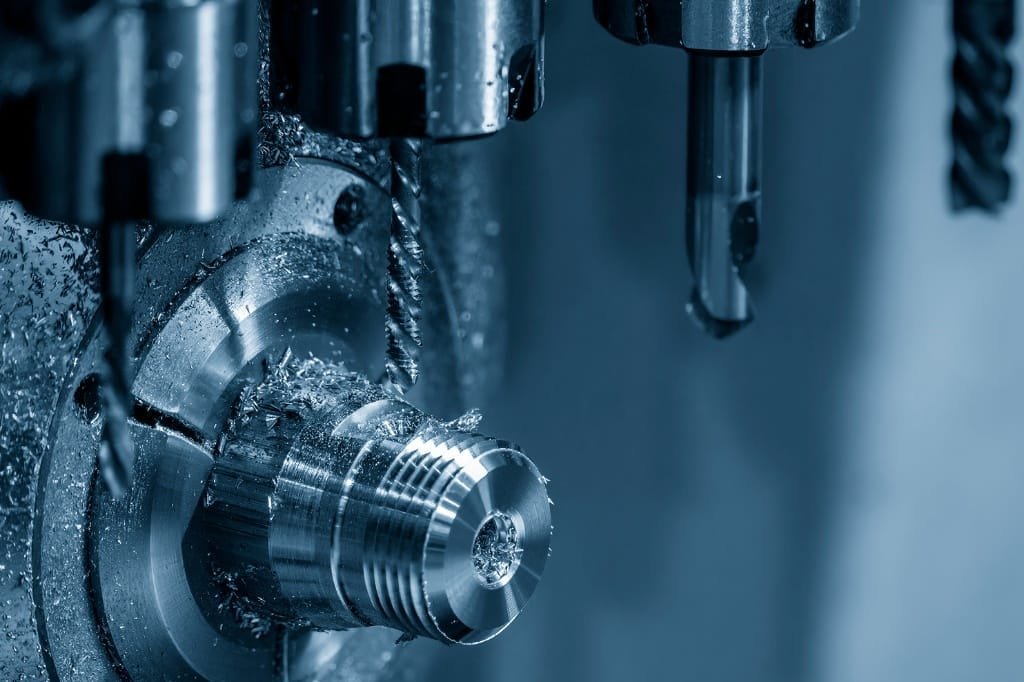
In turning, the workpiece rotates while a cutting tool removes material. Choose turning when the key dimensions and surfaces are organized around a central axis, especially when the part includes a sequence of diameters, shoulders, grooves, or threads.
Geometry and features that favor turning
A turned profile may include a cylindrical outside diameter, an internal bore, a taper, a groove, or an external or internal thread. The drawing often makes the axis of rotation clear through a centerline and diameter dimensions. If the functional fit depends on concentric diameters or a specified shoulder location, identify those relationships and datums clearly for the manufacturing review.
Typical turning examples
Shafts, bushings, sleeves, pins, and many threaded components are typical turning candidates. A stepped shaft with several diameters, a groove, and an end thread is a straightforward example of rotational geometry. A slender shaft or small-diameter connector may also need a discussion of workholding and support, particularly when its length and feature arrangement make rigidity important.
Drawing check
Do not assume every round-looking component is a turning-only part. Flats, cross-holes, non-concentric features, and precisely oriented slots may require milling or turn-mill capability after the rotational surfaces are made.
Drawing Clues That Decide the Process
A process decision is more reliable when you read the drawing as a connected system: geometry, datums, tolerances, surface requirements, material, and quantity all matter. Use the following review points before choosing a route or requesting a quotation.
Read the datum scheme
Identify the surfaces or axes that locate the part in its assembly. If a hole pattern is positioned from two flat edges, milling may align naturally with those references. If concentric diameters and shoulder positions control fit, the turning axis may be the more important reference. When a drawing uses both types of relationships, note which features must remain aligned across setups.
Check tolerances and finish requirements
Separate general tolerances from the dimensions that control assembly or function. Pay particular attention to fits, geometric tolerances, thread callouts, surface finish symbols, and any explicit requirements for concentricity, flatness, or perpendicularity. A tight tolerance on one feature may influence how the part is held, which operation creates it, and how it will be inspected.
Consider stock and quantity
The starting material can affect the practical route. Bar stock may suit a rotational component, while plate or block stock may better match a prismatic part. Order quantity also affects the balance between setup effort, machine choice, and repeatability. A route that makes sense for a prototype may not be the most suitable one for recurring production, so include expected order pattern when you ask for a process review.
| Drawing clue | Likely process direction | What to verify |
|---|---|---|
| Flat faces, pockets, slots, and edge-located hole patterns | CNC milling | Face access, workholding, and datum references |
| Concentric diameters, shoulders, grooves, or axis-based threads | CNC turning | Axis definition, fits, and shoulder relationships |
| Turned body plus flats, cross-holes, or milled features | Turn-mill or multiple operations | Feature orientation, datum transfer, and operation sequence |
| Tight functional dimensions or specified surface finish | Requires drawing-based review | Inspection method and acceptance requirements |
-
1
Mark the primary shape
Decide whether the component is mainly prismatic, rotational, or a genuine combination of both.
-
2
Identify critical relationships
Highlight dimensions and geometric controls that govern fits, alignment, sealing, or assembly.
-
3
Map features to setups
Consider which faces or axes need to be located together, and where a second operation may be needed.
-
4
Confirm supply context
Share the material, quantity, and whether the requirement is a prototype, repeat order, or production run.
Hybrid and Secondary Ops
Some drawings do not fit neatly into a milling-versus-turning choice. Turn-mill machining combines rotational cutting with milling features, while separate milling and turning operations can also be planned when the part and production requirements support that route. The best choice depends on feature relationships, machine access, and how the part can be located securely.
When to combine processes
Consider a combined route for a shaft with milled flats, a turned connector with cross-holes, or a cylindrical component with a non-concentric slot. If the turned and milled features have a critical positional relationship, discuss how the datum will be maintained as the part moves between operations—or whether a suitable turn-mill process can address more features in a coordinated setup. For rotational process basics, see Turning.
Plan the operation sequence
Operation order can influence both access and inspection. A practical review often asks which surfaces should be established first, how the component will be held for later features, and whether any secondary work is needed after machining. We also clarify which dimensions require verification and how the drawing defines acceptance.
Manufacturing note
At YJCNC, our machining resources include CNC milling, CNC turning, turn-mill machining, and Swiss-type machining. We review custom parts against the supplied drawing and technical requirements; the appropriate route depends on the specific component and project.
Shop-floor decision examples (mid-size CNC)
On a recent bracket family, the envelope was a 180 × 120 × 25 mm plate with a pattern of M6 holes and a shallow pocket. That geometry is milling-first: planar datums, rectangular stock, and no useful centerline. We held ±0.05 mm on hole positions from two edges with a soft-jaw vise and a 3-axis program—typical for YJCNC prototype lots with no MOQ.
By contrast, a Ø28 mm stepped shaft with three diameters, a snap-ring groove, and an M16 thread is turning-first. The functional surfaces share one axis; milling would only add cost. When the same shaft also needs two wrench flats and a cross-hole, we evaluate live tooling versus a second mill op. For lots under a few dozen, either route can be right; DFM from the drawing decides.
| Drawing clue | Lean milling | Lean turning | Often hybrid |
|---|---|---|---|
| Primary envelope | Block / plate / housing | Cylinder / cone along one axis | Turned body + prismatic features |
| Datums | Planar edges / faces | Centerline + faces of revolution | Axis + flats / keyways |
| Typical tol. focus | True position, flatness | Diameter, concentricity, runout | Both families on one print |
| YJCNC lead time* | Often 3–7 days in stock Al/steel | Often 3–7 days on bar | May add a day for second op |
*Lead times assume material availability and standard finishes; tight aerospace or medical documentation can extend review time even when cutting time is short.
FAQ on this page answers buyer edge cases (inspection, quantity breakpoints, surface finish) rather than repeating the milling-versus-turning definitions above.
FAQ
Can one drawing legitimately need both milling and turning?
Yes. Turned diameters with milled flats, keyways, or cross-holes are common. We quote turn-mill or a planned two-op route after reading the datum scheme—not from a blanket preference.
Does higher quantity automatically switch the process?
Not by itself. Quantity can justify dedicated workholding or bar-fed turning, but geometry still decides whether the primary spindle should rotate the tool or the part.
What should I send for a fast DFM reply?
PDF/STEP, material & temper, critical tolerances, finish, and target quantity. YJCNC has no MOQ and can review even early drawings.
How do surface-finish callouts change the choice?
Fine finishes on diameters often favor turning or grinding; fine finishes on pockets favor careful milling parameters. The process follows the face that carries the finish note.
Conclusion
For a drawing dominated by flat faces, pockets, slots, and edge-located holes, start by considering CNC milling. For a part built around a centerline with concentric diameters, shoulders, grooves, or threads, start by considering CNC turning. When both feature families matter, compare a turn-mill route with a planned sequence of operations.
The final decision should account for datums, functional tolerances, stock, quantity, workholding, and inspection—not shape alone. At YJCNC, we work with customers to review drawings and select a suitable machining approach for prototypes, repeat orders, and production projects, subject to project requirements.
Drawing-Based Manufacturing Support
YJCNC is certified to ISO 9001 (HIC241500), ISO 14001 (HIC241501), AS9100D/EN9100 (CN044900), ISO 13485 (04526MDQ00014R100), and IATF 16949 (0565487). Confirm which certificates apply to your drawing package and end-use before release.
Need help choosing the right process?
Contact YJCNC to discuss your drawing, machining requirements, or quotation request. We can review whether milling, turning, turn-mill, or another suitable route fits your component and order needs.
Contact YJCNC