CNC Machining Guide
Jigs and Fixtures in CNC Machining: Types & Design Tips
Learn how jigs and fixtures differ, the main types used in CNC machining, practical design principles, material choices, and the production conditions that make custom workholding worthwhile.
In the shop, workholding is part of the process—not an accessory. We use jigs and fixtures to make a part easier to machine consistently, but the right design depends on whether the tool needs guidance, the workpiece needs secure location, or both.
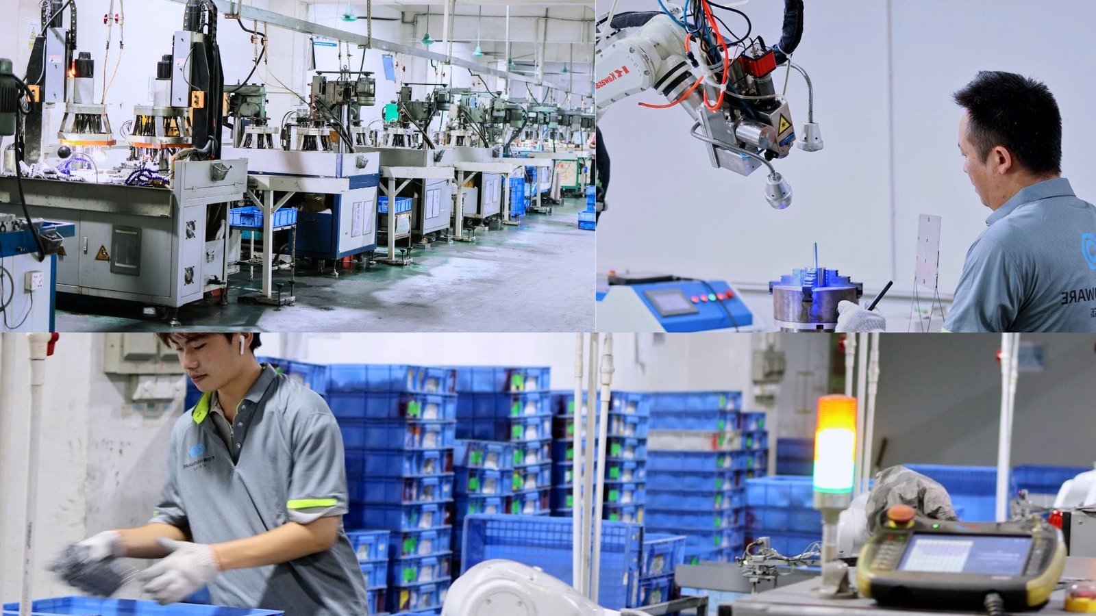
What Are Jigs and Fixtures?
A jig guides a cutting tool relative to the work, much like a stencil guides a pencil; a fixture locates and holds the workpiece, much like a vise keeps a board steady while you cut it. Both help control the relationship between the tool and the part, but their primary jobs differ: a jig guides the tool, while a fixture supports and secures the workpiece.
What Is a Jig?
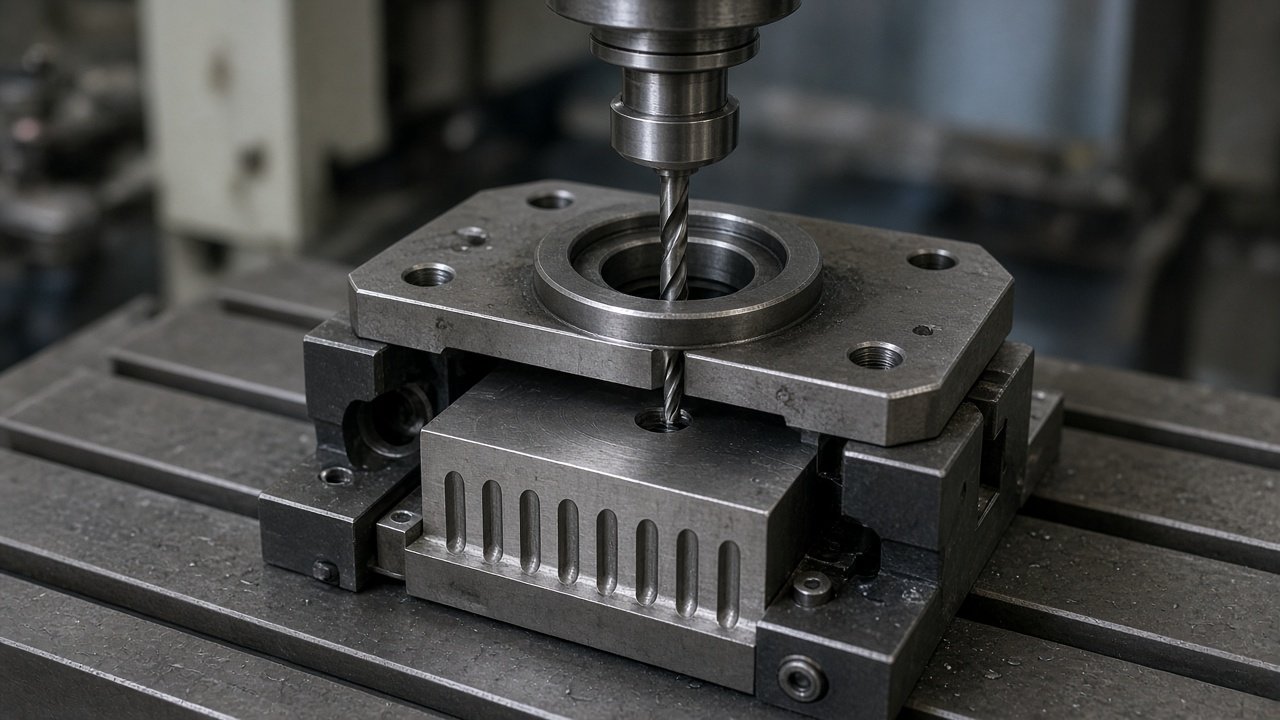
A jig controls where a tool enters or travels relative to a part. A drill jig, for example, can use hardened bushings to guide a drill into repeatable hole locations. Jigs often hold or guide the tool rather than clamp the part; the workpiece still needs suitable support and restraint.
What Is a Fixture?
A fixture locates, supports, and secures a workpiece in a known position during an operation. Fixtures are used on CNC mills and lathes, as well as during inspection, where a part must be held consistently for measurement. They establish a dependable reference without necessarily guiding the cutting tool.
Key Differences Between Jigs and Fixtures
People sometimes use “jig” and “fixture” interchangeably because both are workholding devices and some designs combine the functions. In common shop terminology, the distinction is whether the device guides the tool or primarily locates and holds the work.
| Comparison | Jig | Fixture |
|---|---|---|
| Primary function | Guides or controls the tool. | Locates, supports, and holds the part. |
| Tool contact | May contact the tool, often through a guide bushing. | Normally avoids contact with the cutting tool. |
| Typical use | Repeatable drilling or tool guidance. | Milling, turning, inspection, and part support. |
| Cost | Can be simple and economical; precision guides add cost. | Ranges from standard workholding to a dedicated assembly. |
| Complexity | Often driven by tool access and guide layout. | Often driven by locating, clamping, rigidity, and access. |
Shop context
Workholding that pays for itself
- We at YJCNC are a mid-size CNC shop with no MOQ—custom fixtures are usually justified when a feature relationship repeats across a batch or when hand location cannot hold the drawing tolerance.
- Soft-jaw or modular vise setups often cover prototype lots in 3–7 days; dedicated plates appear when cycle time or datum transfer cost dominates.
- Fixture design starts from the drawing’s datum scheme, not from a generic clamp catalog.
Why Jigs and Fixtures Matter in CNC Machining
A repeatable setup reduces variation introduced by manual positioning. When each blank seats against the same datums and is clamped in a controlled way, the machine can produce more consistent feature locations from part to part. That consistency supports easier inspection, more predictable assembly, and less dependence on an operator’s feel.
Good workholding can also shorten setup and handling time, allow more than one face or part to be machined per setup, and reduce the chance of a workpiece shifting during a cut. Secure clamping and sensible chip protection are important safety measures, while stable location helps prevent scrap caused by movement or inconsistent positioning.
Tolerance note
A fixture cannot make an unstable process accurate by itself. Its locating repeatability, rigidity, machine condition, tool behavior, thermal effects, and measurement method all contribute to the result. For tight tolerances, review the full process capability rather than treating fixture accuracy as the only control.
Common Types of Jigs
Jig designs range from a simple guide plate to a multi-position assembly. Choose the least complicated arrangement that reliably controls the tool and supports the expected production method.
Drilling and Boring Jigs
Drilling jigs commonly use replaceable bushings to guide a drill at a defined location and angle. A properly designed plate can help maintain a hole pattern across repeated parts, especially when operators load and unload blanks frequently. Boring or reaming applications may also use a guide arrangement where the process benefits from controlled alignment; the guide material and clearance must suit the tool and operation.
Template and Plate Jigs
A template or plate jig uses a shaped plate, openings, or reference edges to establish tool position. It can be a practical, low-cost option for prototypes, repair work, and small batches when a dedicated automated setup is not justified. Make sure the plate is located consistently and that the operator can see and clear chips from the working area.
Indexing and Rotary Jigs
Indexing and rotary jigs position a part at multiple defined angles or stations. They can reduce repeated setups for multi-face work, provided the indexing mechanism returns to its position reliably and is locked securely before cutting. Consider how the part is loaded, how the index is verified, and whether the machine tool can reach each face without interference.
Box and Leaf Jigs
A box jig surrounds or encloses a workpiece, supporting it while allowing access to several faces. A leaf jig uses a hinged section that opens for loading and closes to establish the tool-guiding position. These designs suit parts with complex hole patterns or multiple drilling directions, but hinges, stops, and guide plates need to remain clean and accurately located.
Common Types of Fixtures
Fixtures span general-purpose devices used across many jobs and dedicated systems built around one part family. The right choice balances changeover effort, rigidity, accessibility, and the cost of making and maintaining the fixture.
Vises and Machine Vises
A machine vise is a versatile starting point for prismatic parts. Select jaws and contact areas that support the work without obstructing the tool path; for thin parts, broad or shaped support may reduce distortion. A standard vise can be less suitable for irregular profiles, fragile surfaces, or parts that cannot tolerate concentrated jaw pressure, so verify seating and clamping before machining.
Chucks, Collets, and Soft Jaws
Chucks and collets hold workpieces for turning and can also locate round stock in suitable milling setups. For nonstandard profiles or more secure engagement, machinists can cut soft jaws to match the part’s shape and gripping length. The jaw profile should support the work, preserve concentricity or alignment as required, and avoid applying excessive force to thin walls.
Vacuum and Magnetic Fixtures
Vacuum workholding can be useful for broad, thin plates when the material and sealed area allow adequate holding force. It becomes risky when the part has leaks, a small contact area, interrupted surfaces, or cutting forces that may lift or slide it. Magnetic fixtures can hold suitable ferrous materials; they are not a general solution for non-ferrous stock, so consider another method for aluminum and other non-magnetic materials.
Dedicated Fixtures
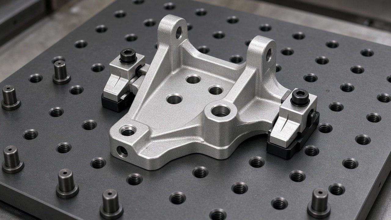
A dedicated fixture is built around a particular geometry or part family. It can provide repeatable loading, strong support at critical areas, and planned access for the production toolpaths. Its value depends on repeat demand and stable part design: a fixture that saves time on a recurring job may be unnecessary overhead for a one-off component.
Modular and Zero-Point Fixtures
Modular systems use reusable baseplates, risers, clamps, and locators that can be rearranged for different jobs. Zero-point systems provide a repeatable interface for moving pallets or fixture plates between stations. Both approaches can cut changeover work when jobs share a machine interface, but the system still needs a verified datum scheme and a documented setup for each part.
Choosing Between a Jig and a Fixture
Start with the manufacturing problem, not the name of the device. A quick decision sequence helps establish whether tool guidance, workpiece restraint, or a combination is required.
- 1
Does the tool need guiding?
If tool entry or position must be physically controlled, evaluate a jig or guided feature.
- 2
Does the part need locating and clamping?
If the work must be restrained against cutting forces, plan a fixture or other suitable workholding.
- 3
Will the process repeat?
For recurring work, compare setup time, quality variation, and maintenance against the cost of a purpose-built solution.
Quick Shop-Floor Checklist
Repeatability: Can every blank seat against the same references?
Access: Can tools, coolant, and chips reach and leave the cutting area?
Safety: Is the part secure, and can the operator load and release it safely?
Payback: Will the solution reduce enough setup time, scrap, or handling effort?
When a Jig Makes Sense
Consider a jig when a repeated hole pattern must stay consistent, a drill or similar tool benefits from physical guidance, or manual marking and positioning create avoidable variation. For a CNC process, the machine program may already control tool position; a jig is most useful when it adds meaningful guidance, supports a manual or secondary operation, or simplifies a repeatable setup.
When a Fixture Wins
Fixtures are the usual focus for CNC milling and turning because the machine controls the programmed tool path while the workholding must locate and restrain the part. A fixture is especially valuable for multi-face machining, parts with limited gripping surfaces, and operations that need a rigid, repeatable setup.
Hybrid Jig-Fixture Designs
A hybrid design combines part location and clamping with a feature that guides or references the tool. For example, a plate can seat a component against repeatable stops while replaceable bushings guide drilling. Combining functions can simplify handling, but it should not obstruct CNC tool access or introduce an unnecessary contact point.
Design Principles for CNC Workholding
A sound workholding design starts with the part’s datums and cutting forces. From there, practical design decisions should protect accuracy, give tools and chips room to move, and make the setup straightforward to repeat.
Locating and Datum Strategy
The 3-2-1 principle is a useful way to think about locating a rigid part: three contacts establish a primary plane, two locate a secondary plane, and one locates the final direction. It is a planning aid, not a substitute for engineering judgment; the part’s geometry, machining sequence, and required degrees of freedom still matter. Select fixture references that correspond to controlled drawing datums or reliable machined surfaces, and avoid locating on rough or variable stock unless the process accounts for it.
Clamping Force and Part Deformation
Place clamps so they push the workpiece into its locators and support points rather than lifting it away from them. Thin walls, soft materials, and long unsupported sections may distort under concentrated force; use broader pads, additional support, or a lower controlled force where appropriate. Check the part after unclamping if springback could affect measured dimensions.
Stability and Rigidity
A flexible base, long unsupported overhang, or poorly supported part can deflect and vibrate under cutting load. Keep the load path short, support the work near the cutting zone when possible, and use a base that mounts securely to the machine. If chatter appears, assess fixture stiffness and contact before changing the workholding force alone; excessive clamping can deform a part without solving an underlying rigidity problem.
Tool Access and Chip Evacuation
Check the complete tool assembly—not just the cutter—for clearance around clamps, fasteners, and fixture walls. Plan coolant delivery and chip escape paths, especially for pockets and deep features where chips can pack against the workpiece. A fixture that traps chips can prevent proper seating on the next load and create a repeatability problem even when its locators are accurately made.
Simplicity, Maintainability, and Interchangeability
Fewer components usually mean fewer places for chips, wear, and assembly mistakes to affect the setup. Use standard fasteners and replaceable wear points where practical, and make the correct orientation obvious. If a locator, pad, or bushing is expected to wear, design it to be replaceable without rebuilding the entire fixture.
Ergonomics and Operator Safety
Consider part weight, grip points, clamp reach, and whether the operator can confirm that the work is fully seated before the cycle starts. Avoid pinch points and loose elements that could be left in the machine. Provide a clear release sequence, and use suitable guarding or machine-door interlocks as required by the machine and shop safety procedures.
Step-by-Step Design Process
We recommend defining the process before drawing fixture hardware. The following sequence helps catch access, datum, and validation issues early.
- 1
Define Machining Operations and Tool Paths
List the operations, their sequence, tool directions, and the faces that must remain accessible. Include loading, unloading, deburring, and inspection considerations—not only the cutting moves.
- 2
Establish Datums and Locating Features
Map drawing datums to accessible surfaces or features on the blank. Decide which features locate the part, which clamps retain it, and how the setup will be referenced back to machine coordinates.
- 3
Verify with CAD and Simulation
Model the part, fixture, tool holders, and relevant machine envelope. Check toolpath and clamp collisions, approach and retract clearance, chip access, and room for the operator to load the work.
- 4
Prototype, Test, and Refine
Run a controlled first setup, check that the part seats and clamps as intended, and inspect critical dimensions on the first article. Record the results, adjust the fixture or method as needed, and confirm the revised process before relying on repeat production.
Materials for Jigs and Fixtures
Material selection affects stiffness, mass, wear, machinability, cost, and thermal response. Match the material to the duty cycle and contact conditions rather than choosing by convenience alone.
Aluminum and Steel Options
6061 aluminum is comparatively easy to machine and lighter than steel, making it useful for fixture plates, prototypes, and setups where reduced mass is helpful. Mild steel is commonly selected when a heavier, more rigid base or durable structural component is needed. Tool steels can suit components that need higher wear resistance or hardness, but may require more demanding machining and finishing operations. Consider rigidity, machine payload, corrosion protection, and thermal behavior for the actual setup.
Hardened and Wear-Resistant Components
Locators, drill bushings, and contact pads are frequent wear points. Hardened or otherwise wear-resistant replaceable components can preserve location over repeated loading and reduce the need to replace a larger fixture assembly. Inspect bushings and locating faces for wear, burrs, and chip damage, since small changes at these interfaces can affect part position.
Polymers and Composites
UHMW and acetal can provide low-friction or non-marring contact surfaces for parts that should not be marked by metal jaws. Other polymers and composites may be suitable for lightweight fixtures or protective inserts. Check the specific material’s stiffness, temperature limits, chemical compatibility, and dimensional stability before using it near heat, coolant, or significant cutting forces.
3D Printing vs. CNC Machining for Jigs and Fixtures
A useful current approach is to print early workholding concepts for fast fit checks, then machine a durable version if the design moves into sustained production. Additive manufacturing offers design freedom, but the printed material and build orientation must suit the loads, temperature, and accuracy requirements of the shop process.
Advantages of 3D Printed Jigs and Fixtures
Printed parts can be turned around quickly for a fit check and can make complex shapes, ergonomic grips, or custom nests without extensive material removal. They can also make design iterations less expensive when the geometry is still changing. For prototypes and light-duty aids, this speed can help a team test loading and access before committing to a machined fixture.
Limitations and Where Machined Parts Still Win
Printed polymers may have lower stiffness, heat resistance, dimensional stability, or long-term wear resistance than a suitable metal fixture. Layer orientation and print process can also affect strength and repeatability. Machined metal remains a strong choice when a fixture must resist substantial cutting loads, maintain critical locating surfaces over repeated use, or operate in a hot or demanding environment.
FDM, SLA, SLS, and MJF Comparison
| Process | Typical characteristics | Possible shop use |
|---|---|---|
| FDM | Accessible thermoplastic printing; visible layer lines and direction-dependent properties are considerations. | Concepts, fit checks, light-duty guides, and handling aids. |
| SLA | Can produce fine detail and a smooth surface; resin properties vary and may be less suitable for impact or heat. | Detailed templates, visual models, and low-load positioning aids. |
| SLS | Powder-bed nylon parts can support complex shapes without the same support strategy as some other processes. | Functional nests and light-to-moderate duty parts, subject to material and load validation. |
| MJF | Powder-bed polymer process suited to complex functional geometries; finish and properties depend on material and process. | Iteration, custom nests, and production aids when performance is tested for the application. |
Accuracy and surface finish are process-, material-, geometry-, and supplier-dependent, so no process name alone guarantees a particular result. For a critical locating interface, measure the printed feature and consider machining or adding a metal insert.
Hybrid Approach: Print First, Machine for Production
A practical workflow is to print a prototype nest or setup aid, test operator access and part seating, and revise the geometry before producing the final fixture. If the validated design will see repeated production use, machine the structural base and precision locating features in an appropriate material; retain printed components for non-critical covers, guides, or replaceable contact pieces where suitable.
When You Need Custom Jigs and Fixtures
Custom workholding becomes worth considering when a recurring process is difficult to repeat with standard equipment, or when a fixture can address a clear quality, safety, or throughput problem.
Signs Your Shop Needs Custom Workholding
Quality varies by operator: Manual alignment or inconsistent clamping changes feature location or part appearance.
Scrap or rework is recurring: Mislocation, movement, or clamp distortion is a repeated cause rather than an isolated event.
Setups take too long: Repeated indicate-and-adjust work is consuming time on recurring orders.
The part is difficult to grip: Complex geometry, thin walls, or multi-face operations require more dependable support.
Handling raises safety concerns: Loading, clamping, or releasing the work is awkward or exposes the operator to avoidable risk.
When Off-the-Shelf Workholding Is Enough
A standard vise, chuck, collet, or modular fixture kit may be entirely appropriate for one-off parts, low-volume jobs, and geometries that load securely without special support. If it meets the tolerance, access, safety, and setup requirements with manageable changeover effort, custom hardware may add cost without enough production benefit.
Advanced Workholding Trends
As shops handle more mixed-part production and automation, fixture design increasingly considers quick changeover, process feedback, and reliable machine tending alongside the traditional requirements for location and rigidity.
Quick-Change and Modular Systems
Quick-change interfaces and modular plates can reduce the time spent rebuilding a setup between jobs. Their benefit is strongest when the machine interface, datum references, and setup documentation are standardized. For mixed-part production, reusable bases can support different fixture tops while preserving a familiar machine-side reference.
Smart Fixtures with Integrated Sensors
Sensors can help detect part presence, confirm a clamp state, or monitor load conditions as part of a broader process-control system. The signal should be tied to a clear response—for example, preventing a cycle from starting when the part is absent—and verified for reliability. Sensors add wiring, protection, and maintenance considerations, so include them only when the process benefits from the information.
Automation and Robotic Loading
Fixtures intended for robots or pallet systems need predictable loading orientation, accessible gripping surfaces, and a repeatable interface to the machine. Design for chip control and part-presence verification, and avoid features that make it possible to load the component incorrectly. The fixture, robot gripper, machine sequence, and safety system should be reviewed as one process.
Applications Across Industries
Workholding priorities vary with part geometry, production volume, material, and the quality system surrounding the process. The fixture should reflect the application rather than a one-size-fits-all design.
Automotive Component Machining
Recurring automotive parts can benefit from dedicated fixtures designed to reduce cycle and changeover time while keeping loading consistent. Multi-part fixtures may improve machine utilization when the process, tool access, and inspection plan support them. Durability and straightforward maintenance matter when the fixture is used repeatedly. See also CNC milling setups for practical context.
Aerospace Precision Parts
Aerospace workholding may need to support tight tolerance requirements, complex geometries, and materials that are demanding to machine. Controlled datum transfer, low-distortion clamping, and documented setup and verification methods are important considerations. The fixture should be validated against the drawing and the process requirements, not assumed to be adequate based on appearance alone.
Medical Device Manufacturing
Medical-device workholding may need to support cleanability, traceability, and handling requirements in addition to dimensional control. Material choice and fixture design should suit the component and the applicable process environment. When supplier quality systems are part of qualification, confirm that the relevant scope, documentation, and inspection controls match the project requirements.
Common Jig and Fixture Problems and Fixes
A fixture problem can show up as a machining symptom, a measurement pattern, or difficulty loading the next part. Use the symptom to guide inspection rather than increasing clamp force or changing offsets without finding the cause.
| Symptom | Likely cause | Practical fix |
|---|---|---|
| Deflection, chatter, or vibration | Flexible base, long overhang, weak support, or cutting forces that excite the setup. | Shorten the load path, support nearer the cut, review clamping, and assess toolpath or cutting conditions. |
| Part position shifts between cycles | Worn or dirty locators, chips under the part, inconsistent datum contact, or incorrect loading. | Clean and inspect contacts, verify datum references, replace worn components, and confirm seating at first-off. |
| Clamp marks or distorted features | Excessive or concentrated force, poor support, or unsuitable contact material. | Adjust clamp force and placement, improve support, or use an appropriate protective pad or insert. |
Deflection, Chatter, and Vibration
If marks, noise, or dimensional variation suggest vibration, check whether the part or fixture can move under cutting load. Improve support and base rigidity where possible, reconsider clamp placement, and review toolpath engagement and cutting conditions with the machining team. More force is not always the answer, particularly if the part is thin or flexible.
Misalignment and Repeatability Issues
Inspect locator faces for wear, burrs, and embedded chips, then confirm that the intended datum surfaces are actually contacting the fixture. Verify the setup reference and first-part measurements before changing machine offsets. If different operators get different results, simplify the loading sequence and add a clear seating check.
Part Damage and Clamp Marks
Marks often point to concentrated force, a hard or contaminated contact surface, or a clamp contacting a cosmetic area. Use a suitable pad or insert, reduce force where safe, and provide support close to the clamping point. Keep protective surfaces clean: trapped chips can leave marks and prevent repeatable seating.
Maintenance and Inspection of CNC Fixtures
Inspect a fixture before use and establish a more detailed periodic check based on its duty, wear points, and quality risk. After machining, remove chips and coolant residue that could interfere with locating surfaces; lubricate moving elements where the design calls for it. Check that clamps move freely and fasteners remain secure.
Inspection Points to Record
Locators and datums: Check condition, cleanliness, and position against the fixture reference.
Clamps and fasteners: Look for looseness, damage, binding, or inconsistent travel.
Wear components: Track bushing, pad, jaw, and contact-surface wear; replace before it affects location.
Verification: Document checks and corrective action when the fixture supports a controlled process.
Cost Considerations and ROI
Compare total lifecycle value, not just the initial build. A dedicated fixture has more upfront design and manufacturing effort but may reduce handling time on a stable, recurring job. Modular workholding costs more than a simple one-off setup in some cases, but reusable components can serve multiple jobs. A printed fixture can be economical for fit trials and light-duty use, while material limits may make it unsuitable for sustained cutting loads. See also quality inspection and measurement for practical context. For terminology, see workholding fixtures.
Illustrative ROI example
Suppose a recurring job runs 400 parts per year and a revised fixture saves 3 minutes of setup and handling per part. That is 1,200 minutes, or 20 hours, of labor and machine availability over the year, before counting any reduction in scrap or rework. Compare that value with the quoted design and fixture cost, then confirm the time saving in a real production trial. These figures are an example only; use your own volume, labor, machine, and quality costs.
Key Takeaways
A jig guides the tool; a fixture locates and holds the workpiece. Some workholding combines both functions.
Start with datums, tool access, and cutting forces. Those decisions drive accurate, stable, and safe workholding.
Match complexity to production need. Standard equipment is often enough for occasional work; custom workholding can pay off when setup time, variation, scrap, or risk recur.
Validate and maintain the setup. CAD checks, first-article measurement, cleaning, and wear tracking help keep a fixture dependable.
When a part or recurring order is difficult to hold consistently, a design review can help identify whether a jig, fixture, modular setup, or standard workholding is the most practical answer.
FAQs
What is the difference between a jig and a fixture?
A jig guides the tool, while a fixture locates and holds the workpiece. For example, a drill jig can use bushings to guide a bit through a hole pattern; a milling fixture holds a bracket in a repeatable position while the CNC machine follows its programmed path.
Can a jig and a fixture be combined?
Yes. A hybrid design can locate and clamp the part while also guiding a tool or referencing a tool path. It is appropriate when combining those functions simplifies a repeat operation without reducing access, safety, or rigidity.
Are 3D-printed jigs strong enough for CNC production?
They can work for fit checks, light-duty guides, nests, and other applications where the material and loads are suitable. Printed polymers may not offer the stiffness, heat resistance, wear life, or dimensional stability needed for heavy or long-running cutting operations. Test the actual material, geometry, and setup under controlled conditions before production use.
When is a custom fixture worth the investment?
It is worth evaluating when repeat volume is meaningful, tolerances are difficult to hold with standard setups, part loading is complex, or setup time and scrap keep recurring. Estimate the potential savings over the expected run and validate them in production rather than relying on assumptions alone.
How accurate do jigs and fixtures need to be?
The required accuracy depends on the part tolerance, datum scheme, machine capability, and process variation. A useful initial rule of thumb is to keep locating uncertainty to a fraction of the part tolerance—often around one-third to one-fifth where practical—but this is not universal. Tolerance stack-up and validation should determine the final requirement.
How long does it take to design and build a custom fixture?
Timing depends on design complexity, material and component availability, machining requirements, and how much validation is needed. A simple fixture may move through design and build in days, while a more complex assembly can take weeks. A realistic schedule includes design review, manufacturing, fit-up, first-article checks, and any refinement—not just machining time.
Discuss Your Project
YJCNC is certified to ISO 9001 (HIC241500), ISO 14001 (HIC241501), AS9100D/EN9100 (CN044900), ISO 13485 (04526MDQ00014R100), and IATF 16949 (0565487). Confirm which certificates apply to your drawing package and end-use before release.
Need help reviewing a CNC machining requirement?
At YJCNC, we work with customers on precision CNC milling, turning, turn-mill, and Swiss-type machined components, from prototype requirements to repeat orders. Share your drawing, material, tolerance, production expectations, and inspection needs so we can review the manufacturing approach with you.